Vehicle sun visors having lighting devices

a technology of sun visor and lighting device, which is applied in the direction of sun visor, lighting and heating apparatus, transportation and packaging, etc., can solve the problems of degrading operability and complicated construction of sun visor, and achieves the effect of simple construction, easy lighting device light intensity setting, and reliably maintaining the set position

Inactive Publication Date: 2005-10-27
KYOWA SANGYO +1
View PDF4 Cites 13 Cited by
  • Summary
  • Abstract
  • Description
  • Claims
  • Application Information

AI Technical Summary

Benefits of technology

[0008] It is accordingly an object of the present invention to teach vehicle sun visors with lighting devices that are simple in construction and improved in operability.
[0009] In one aspect of the present teachings, vehicle sun visors are taught that include a visor body, a mirror mounted to the visor body, and a mirror cover slidably movable relative to the visor body along a reflective surface of the mirror. The mirror cover is movable between a closed position for substantially covering the reflective surface of the mirror and an opened position for uncovering the reflective surface. A lighting device serves to illuminate a driver or a passenger when using the mirror (i.e., the operator of the mirror may be illuminated). A light control device serves to turn the lighting device from off to on as the mirror cover slides from the closed position to the opened position. The light control device also serves to control the intensity of the light emitted from the lighting device in response to the position of the mirror cover.
[0010] Therefore, the light control device serves as an ON / OFF switch for the lighting device and also serves as a control switch for controlling the intensity of light emitted from the lighting device. As a result, the sun visor may have a simple construction while having the same functionality as dual independent switches.

Problems solved by technology

Therefore, the construction of the sun visor is complicated.
In addition, the operability is degraded because each of the above switches must be separately operated.

Method used


Image

  • Vehicle sun visors having lighting devices
  • Vehicle sun visors having lighting devices
  • Vehicle sun visors having lighting devices

Examples


first representative embodiment

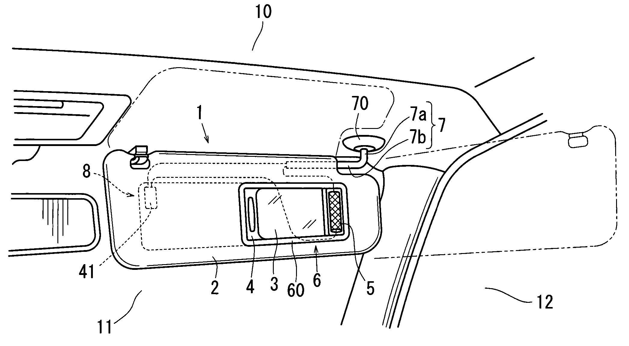
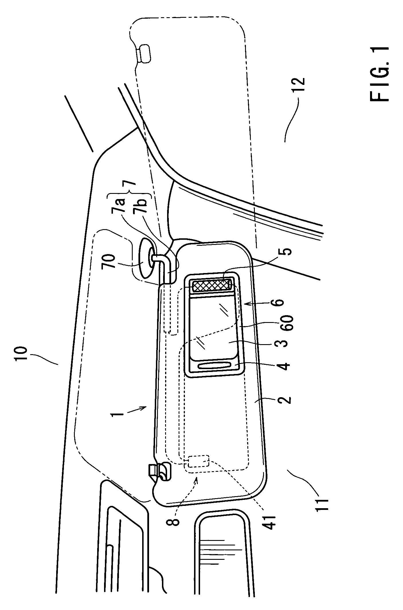
[0034] A first representative embodiment of the present invention will now be described with reference to FIGS. 1 to 10. Referring to FIG. 1, a vehicle sun visor 1 generally includes a rectangular plate-shaped visor body 2, a support rod 7 for supporting the visor body 2, and a bracket 70 for mounting the support rod 7 to a vehicle cabin ceiling 10. A mirror unit 6 is attached on one of the opposing side surfaces of the visor body 2. A lighting device 5 may be mounted on the mirror unit 6.

[0035] The support rod 7 has a substantially L-shaped configuration and includes a vertical rod portion 7a and a horizontal rod portion 7b. The horizontal rod portion 7b is inserted into the visor body 2 in a position adjacent to the upper edge of the visor body 2. The horizontal rod portion7b pivotally supports the visor body 2 about an axis of the horizontal rod portion 7b. The vertical rod portion 7a is rotatably mounted to the vehicle cabin ceiling 10 via the bracket 70.

[0036] Therefore, as t...

second representative embodiment

[0053] The second representative embodiment will now be described with reference to FIGS. 11 and 12. The second representative embodiment is different from the first representative embodiment in the construction of the light control device 8. In other respects, the second representative embodiment is the same as the first representative embodiment.

[0054] Referring to FIG. 12, a light control device 8A has a pair of body electrodes, 90 and 91, mounted to the rear surface of the shell 2a, and a cover electrode 92 mounted to the mirror cover 4. The body electrodes 90 and 91 are aligned with each other in the sliding direction of the mirror cover 4 and are spaced apart from each other in the sliding direction. The cover electrode 92 is made of a leaf spring type of material for example and extends along the sliding direction. The cover electrode 92 has a central mount portion 92e secured to the mirror cover 4. In addition, the cover electrode 92 has two resilient portions 92c and 92d a...

third representative embodiment

[0056] The third representative embodiment will now be described with reference to FIGS. 13 and 14. The third representative embodiment is different from the first representative embodiment in the construction of the light control device 8. In other respects, the third representative embodiment is the same as the first representative embodiment.

[0057] Referring to FIG. 13, a light control device 8B has a pair of body electrodes, 93 and 94, mounted to the rear surface of the shell 2a, and a cover electrode 41 mounted to the mirror cover 4. The body electrodes 93 and 94 extend parallel to each other in the sliding direction of the mirror cover 4 in the same manner as the body electrodes 23 and 24 of the first representative embodiment. However, one of the body electrodes, the body electrode 94 for example, is made of a material having a small electrical resistance that is negligible in comparison with a predetermined electrical resistance given by the material of the other body elect...


PUM


Abstract

A vehicle sun visor includes a visor body, a mirror mounted to the visor body, and a mirror cover slidably movable relative to the visor body along a reflective surface of the mirror between a closed position substantially covering the reflective surface of the mirror and an opened position for uncovering the reflective surface. A lighting device serves to illuminate a driver or a passenger when the mirror is used. A light control device serves to turn the lighting device from off to on as the mirror cover slides from the closed position to the opened position. The light control device also serves to control the intensity of light emitted from the lighting device in response to the position of the mirror cover.

Description

[0001] This application claims priority to Japanese patent application serial number 2004-131626, the contents of which are incorporated herein by reference. BACKGROUND OF THE INVENTION [0002] 1. Field of the Invention [0003] The present invention relates to vehicle sun visors having lighting devices in conjunction with mirrors and mirror covers. [0004] 2. Description of the Related Art [0005] Conventionally, various types of sun visors are known, such as a sun visor disclosed in Japanese Laid-Open Patent Publication No. 7-276984. The sun visor of this publication has a visor body and a mirror unit associated with the visor body. The mirror unit includes a mirror and a mirror cover that is vertically pivotally mounted to an upper edge of the mirror. The mirror cover can move between an upwardly pivoted position (i.e., an opened position) in order to uncover the reflective surface, and a downwardly pivoted position (i.e., a closed position) in order to cover the reflective surface. [...

Claims


Application Information

Patent Timeline
Patent Type & Authority Applications(United States)
IPC IPC(8): B60J3/02B60Q1/00B60Q3/02
CPCB60Q3/0226B60Q3/0296B60Q3/0293B60Q3/252B60Q3/80B60Q3/82
Inventor OGAWA, HIROHITO
Owner KYOWA SANGYO
Why Eureka
Try Eureka