Balanced transmitting apparatus

a transmitting apparatus and balanced technology, applied in the direction of pulse manipulation, pulse technique, line-transmission details, etc., can solve the problems that the generation of common mode current cannot be reduced, and the effect of sufficiently suppressing the common mode current cannot be achieved

Inactive Publication Date: 2005-10-27
PANASONIC CORP
View PDF6 Cites 32 Cited by
  • Summary
  • Abstract
  • Description
  • Claims
  • Application Information

AI Technical Summary

Benefits of technology

[0019] The invention has been carried out in view of the above-described situation of the background art and it is an object thereof to provide a balanced transmitting apparatus capable of suppressing an unbalance state even when an unbalance component is present in transmission lines.

Problems solved by technology

That is, when signals having the same amplitude and inverse phases are superposed on respectives of the pair of lines, although radiation components radiated from the respective lines are canceled by each other when a balanced state is maintained, in an unbalance state, there is a case in which the radiation components are not canceled by each other completely but the radiation components leak to outside.
In the case of lines having a high balance (for example, lines exclusive for communication), the common mode current on the lines are sufficiently suppressed from being generated and therefore, the problem of radiation is not posed.
However, when lines having a comparatively low degree of balance are used as communication lines, even when the degree of balance of the transmission signal is promoted, generation of the common mode current cannot necessarily be reduced.
That is, since the communication lines per se are provided with an unbalance characteristic, there is a case in which an effect of sufficiently suppressing the common mode current cannot be achieved by the technology of the background art of “promoting a degree of balance of the transmission signal per se”.

Method used


Image

  • Balanced transmitting apparatus
  • Balanced transmitting apparatus
  • Balanced transmitting apparatus

Examples


first embodiment

[0064] According to the embodiment, an explanation will mainly be given of an example of a constitution of generating a suppression signal by an analog signal processing and superposing the suppression signal on a transmission signal.

[0065]FIG. 20 is an outlook perspective view showing a balanced transmitting apparatus (front face) and FIG. 21 is an outlook perspective view showing the balanced transmitting apparatus (rear face). As shown by FIGS. 20 and 21, a balanced transmitting apparatus 300 according to the embodiment is a modem. The balanced transmitting apparatus 300 is provided with a cabinet 301. As shown by FIG. 20, the front face of the cabinet 301 is provided with a display portion 306 of LED (Light Emitting Diode) or the like. As shown by FIG. 21, the rear face of the cabinet 301 is provided with a power source connector 302, a modular jack 303 for LAN (Local Area Network) of RJ45 or the like and a Dsub connector 304. As shown by FIG. 21, the power source connector 302...

second embodiment

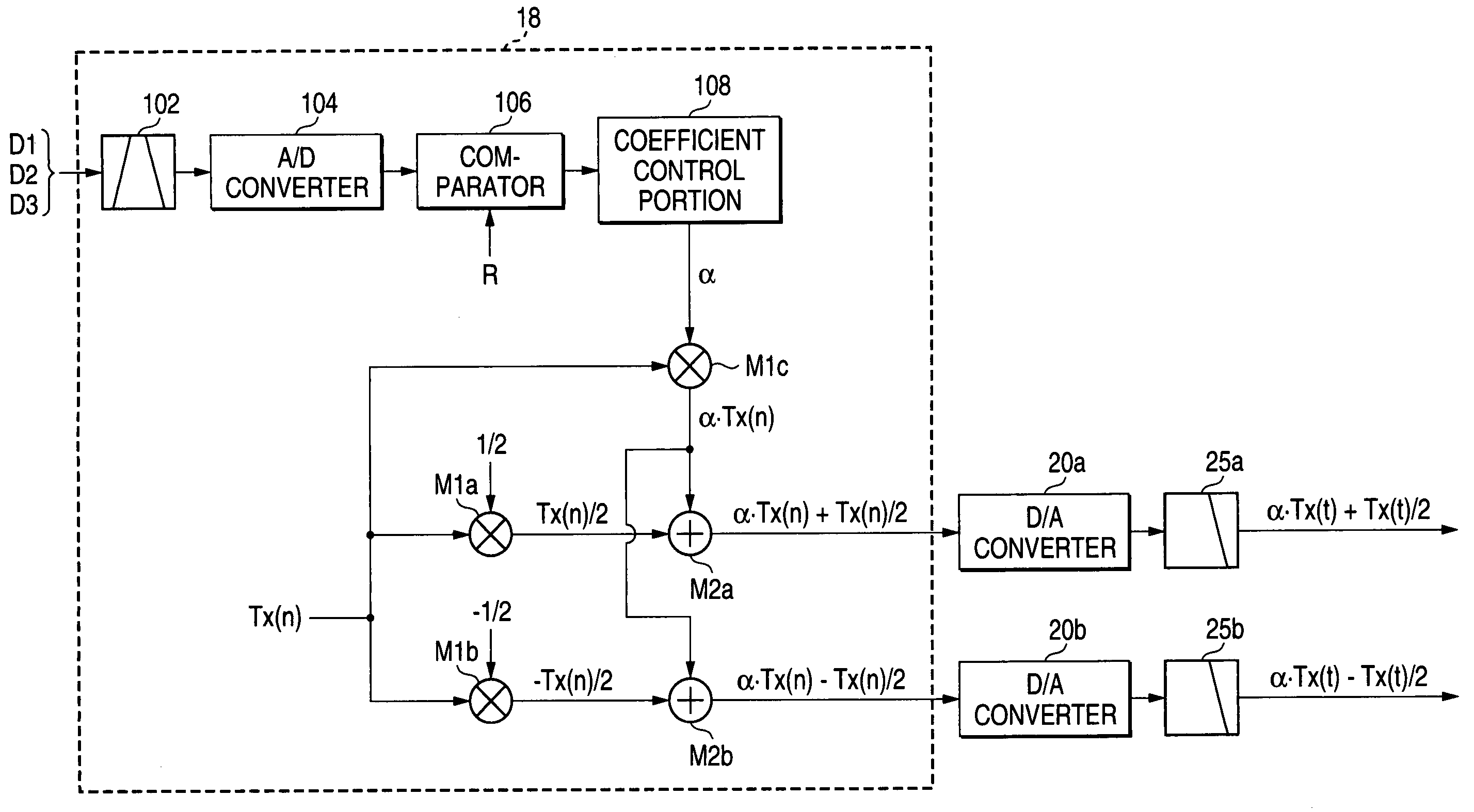
[0083]FIG. 12 is an outline constitution diagram showing a portion of an inner constitution of a balanced transmitting apparatus according to a second embodiment, showing an example of a constitution of a balanced transmitting apparatus when a suppression signal is realized to generate and superpose by using a digital signal processing.

[0084] As shown by FIG. 12, the transmission data generating portion 18 (shown by being surrounded by a dotted line in the drawing) is provided with the band pass filter 102 for removing unnecessary signals out of band included in the unbalance detecting signals DI through D3, the A / D converter 104, the comparator 106 for comparing the level of the unbalance detecting signal with the reference value (R) and outputting the result of the comparison, the coefficient control portion 108 for generating the correction coefficient a) based on the signal showing the result of comparison by the comparator 106, the multiplier M1c for generating the suppression...

third embodiment

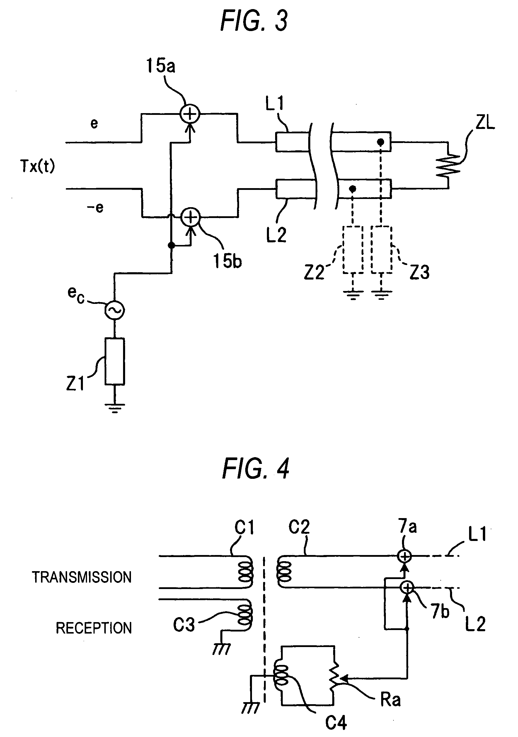
[0101]FIG. 15 is an outline constitution diagram showing a portion of an inner constitution of a balanced transmitting apparatus according to a third embodiment, showing other example of a constitution of a balanced transmitting apparatus when a suppression signal is realized to generate and superpose by using a digital signal processing. According to the third embodiment, a suppression signal is provided with a characteristic of suppressing a characteristic of a frequency characteristic or the like of a system including at least one of communication lines, an unbalance detector, and a transmission data generating portion.

[0102] Further, constituent elements similar to those of the second embodiment are attached with the same notations. The balanced transmitting apparatus of the embodiment is provided with an equalizer 200 having a characteristic inverse to a frequency characteristic of a system including communication lines, an unbalance detector, a transmission data generating po...


PUM


Abstract

A balanced transmission signal Tx (t) (voltage e, −e) is applied to a transmission line (L1, L2), a suppression signal (ec) is generated from a common mode suppression signal source (ec), and the suppression signal (ec) is superposed on respectives of balanced transmission signals via adders (15a, 15b). By pertinently controlling a level of the suppression signal (ec), voltage levels and phases of respectives of the transmission signals transmitted to the transmission lines (L1, L2) are controlled.

Description

BACKGROUND OF THE INVENTION [0001] The present invention relates to a balanced transmitting apparatus. [0002]FIG. 18 is a view showing a current model on a transmission line. The transmission line is constituted by transmission lines (L1, L2) comprising a pair of conductors balanced relative to the earth ground. [0003] In FIG. 18, a pair of voltage sources (e10, e20) are provided at left ends of the transmission lines. Characteristics of waveform, amplitude, phase and the like of e10 and e20 are equal and voltages generated from the respective voltage sources (e10 , e20) (respective voltages are designated by notation “e”) are applied to the respective lines (L1, L2). [0004] A load impedance (regular load) ZL is provided at right ends of the transmission lines. Differential (normal) mode currents (+Id, −Id) directed inverse to each other flow in the transmission lines (L1, L2). [0005] Incidentally, parasitic impedances (impedances to the ground) Z1 through Z3 are interposed between ...

Claims


Application Information

Patent Timeline
Patent Type & Authority Applications(United States)
IPC IPC(8): H04B3/30H04B3/54H04B3/56
CPCH04B3/30H04B3/54H04B2203/5491H04B2203/5483H04B3/56
Inventor YAMASHITA, AKIHIROICHIHARA, FUMIOHANADA, TSUNEHIROOISHI, MUTSUHIKOWAKISAKA, TOSHIYUKIMAKI, MASAHIRO
Owner PANASONIC CORP
Why Eureka
Try Eureka