DC-DC converter

a dc converter and converter technology, applied in the direction of electric variable regulation, process and machine control, instruments, etc., can solve the problems difficult to obtain things with good core characteristics, and difficult to cope with applications requiring a capacity smaller than its large capacity, etc., to achieve the effect of increasing the conversion capacity of dc converters

Inactive Publication Date: 2006-05-30
NISSIN ELECTRIC CO LTD
View PDF5 Cites 17 Cited by
  • Summary
  • Abstract
  • Description
  • Claims
  • Application Information

AI Technical Summary

Benefits of technology

[0020]Therefore, the invention is proposed in view of the problems, and an object of the invention is to provide a DC—DC converter which can prevent an output current of a DC—DC converter from becoming an unbalance state even when there is a slight difference in output voltage of each conversion circuit part in the case of increasing a conversion capacity of the DC—DC converter.
[0024]In a DC—DC converter according to the invention, by providing n groups of inverter units comprising a pair of conversion circuit parts and a pair of transformers with respect to a DC power source, a conversion capacity of the DC—DC converter can be increased. In the case of increasing the conversion capacity of this DC—DC converter, by connecting the secondary sides of the one transformers in the n groups of the inverter units in series among the n groups and also connecting the secondary sides of the other transformers in series among the n groups, even when there is a slight difference in output voltages of each conversion circuit part, output shares of the secondary sides of one transformers and the secondary sides of the other transformers can be equalized, so that an output current of the DC—DC converter does not become an unbalance state.
[0027]That is, by placing one transformers and the other transformers in alternate arrangement so that the arrangement end point is fed back to the arrangement start point, if the secondary sides of the transformers are connected in series among n groups via the wires, leading of the lead wire in the transformers located at the arrangement start point can be brought close to leading of the lead wire out of the transformers located at the arrangement end point and thus the wiring work such as routing of the lead wires can be simplified.

Problems solved by technology

That is, in the case of a DC—DC converter with a small single device capacity, it can cope with various capacities requiring a capacity larger than its small capacity and has flexibility, but in the case that a single device capacity is large, it becomes difficult to cope with applications requiring a capacity smaller than its large capacity.
Also, in the case of using a semiconductor device with large voltage and current in components forming the DC—DC converter, it was very difficult to obtain a semiconductor device with high speed and high performance, or in the case of using a large-size transformer, it was difficult to obtain things with good core characteristics.
Thus, the means for increasing a single device capacity of the DC—DC converter is undesirable because there are the problems described above.
An output current of the DC—DC converter increases or decreases by this cross current and an unbalance state occurs and thereby overcurrent occurrence is caused.
However, bad effects that a control circuit becomes complicated in the former method and an increase in component costs is caused in the latter method occur respectively.
However, if the plural inverter units IU are provided, the number of the transformers Tr1, Tr2 included in the inverter units IU are increased, and thus wiring work for connecting the secondary side of the plural transformers Tr1, Tr2 to the pair of the rectification circuit parts 3, 4 can be complicated.

Method used


Image

  • DC-DC converter
  • DC-DC converter
  • DC-DC converter

Examples


Embodiment Construction

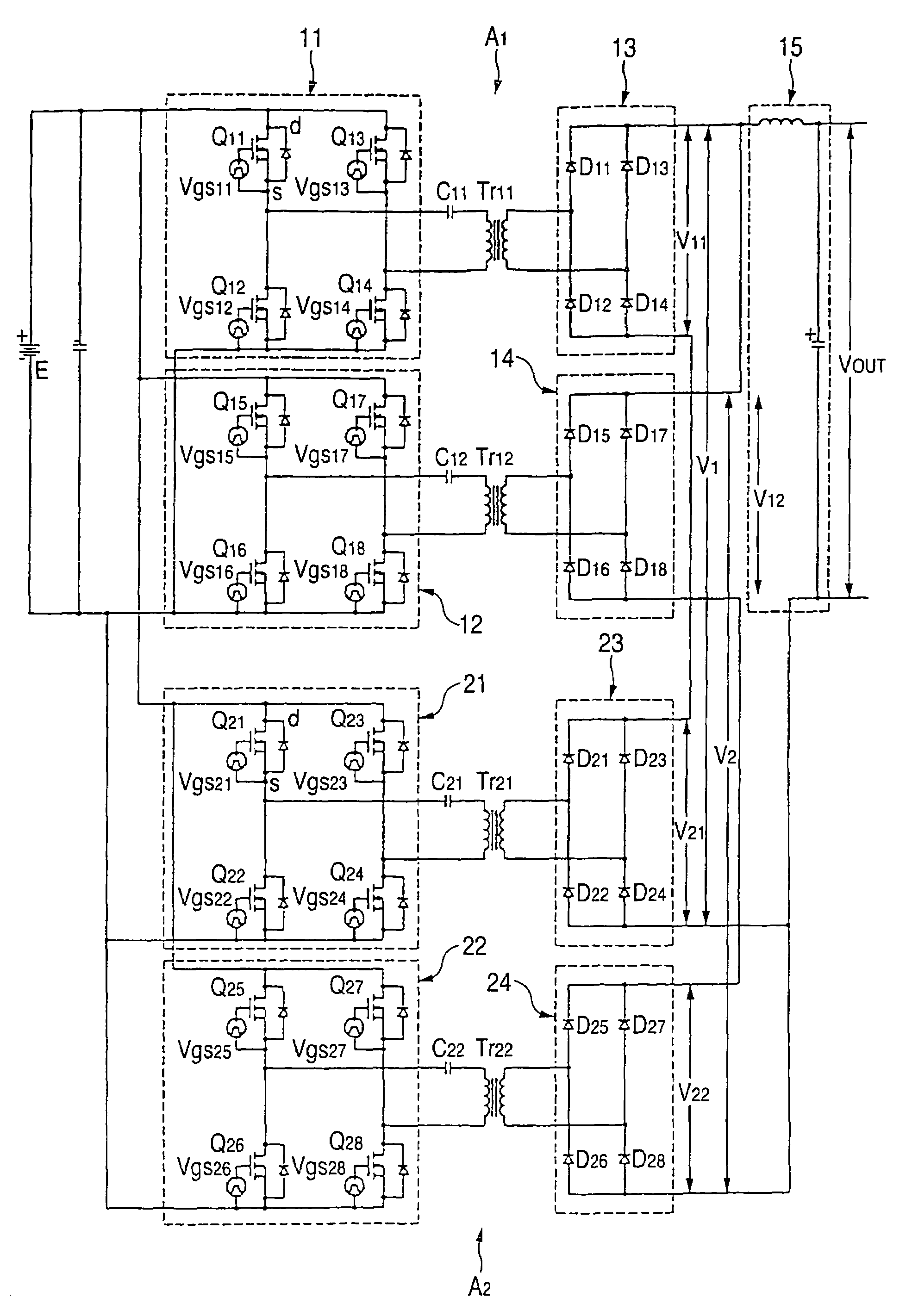
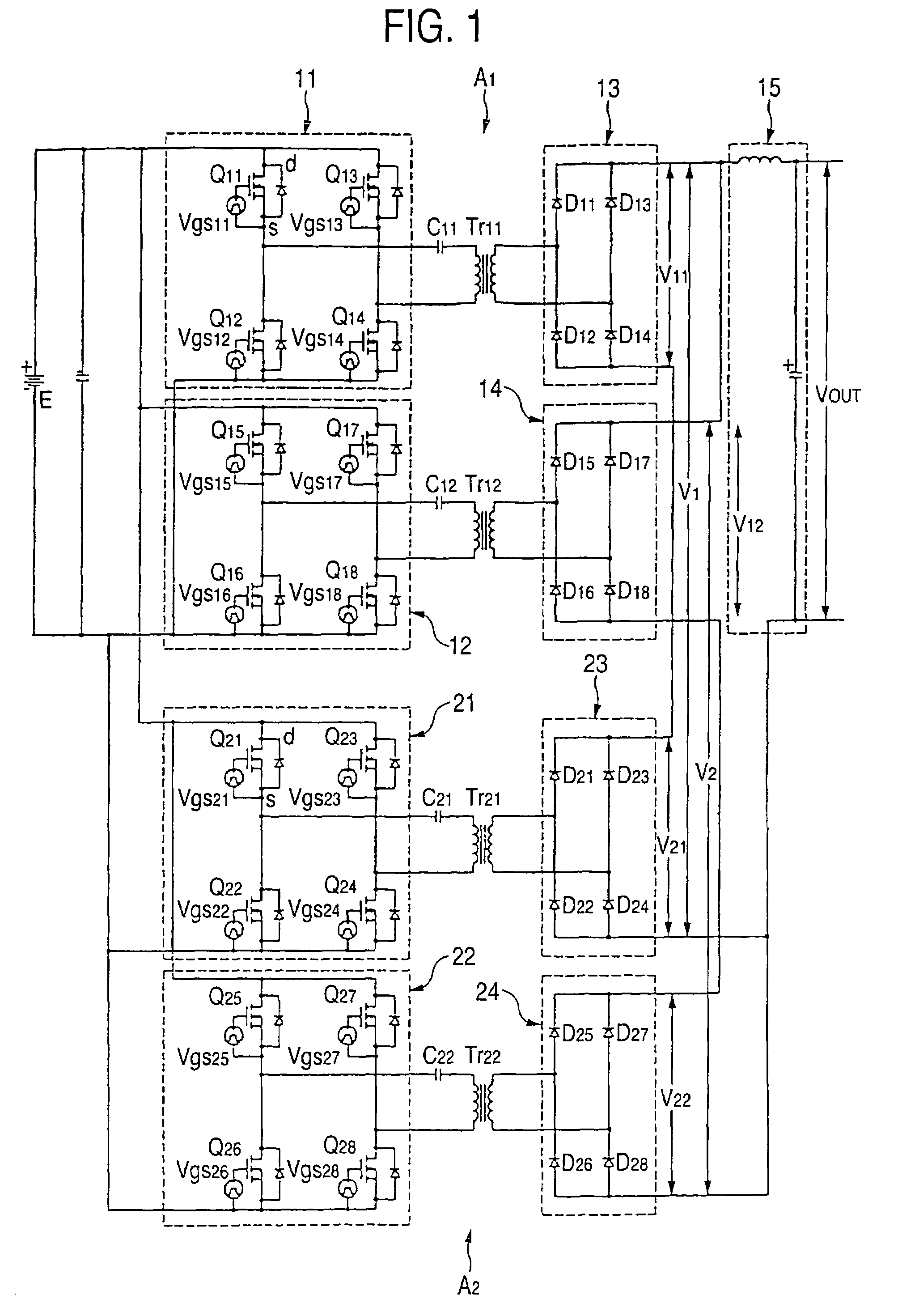
[0051]FIG. 1 is a circuit diagram of a DC—DC converter in an embodiment of the invention.

[0052]The DC—DC converter of this embodiment provides a circuit configuration in which n groups, for example, two groups of unitary units A1, A2 are connected in parallel with a DC power source E. Incidentally, three or more groups of unitary units can be provided.

[0053]One unitary unit A1 provides a following configuration. That is, a pair of conversion circuit parts 11, 12 converts a power source voltage of the DC power source E into an AC by two pairs of switching elements Q11, Q14, Q12, Q13 and Q15, Q18, Q16, Q17 (for example, MOS-FET, bipolar transistor or IGBT) of a full bridge configuration. The pair of conversion circuit parts 11, 12 are connected in parallel with the DC power source E. Rectification circuit parts 13, 14 made of two pairs of diodes D11, D14, D12, D13 and D15, D18, D16, D17 are provided to the output sides of each of the conversion circuit parts 11, 12 through transformer...


PUM


Abstract

A circuit configuration in which a pair of conversion circuit parts for converting a power source voltage of a DC power source into an AC by two pairs of switching elements made of a full bridge configuration and a pair of transformers is used as inverter units. The n groups of the inverter units are provided with respect to the DC power source, and a secondary side of one transformer of each of the inverter units are connected in series among the n groups and also a secondary side of the other transformer are connected in series among the n groups.

Description

CROSS REFERENCE TO RELATED APPLICATIONS[0001]This application is a Continuation-In-Part of U.S. application Ser. No. 10 / 642,681, filed Aug. 19, 2003 now abandoned, which claimed the priority of Japanese Patent Application No. 2002-242267, filed on Aug. 22, 2002, the contents of which are incorporated herein by reference.BACKGROUND OF THE INVENTION[0002]1. Field of the Invention[0003]The present invention relates to a DC—DC converter, and particularly to a DC—DC converter which is used in a DC power source circuit and converts a power source voltage of a DC power source into a different DC voltage.[0004]2. Description of the Related Art[0005]For example, one example of a DC—DC converter used in a DC power source circuit is shown in FIG. 18.[0006]The DC—DC converter shown in FIG. 18 comprises a pair of conversion circuit parts 1, 2, two transformers Tr1, Tr2, a pair of rectification circuit parts 3, 4, and an LC smoothing circuit part 5. The pair of conversion circuit parts 1, 2 have ...

Claims


Application Information

Patent Timeline
Patent Type & Authority Patents(United States)
IPC IPC(8): H02M3/158H02M3/337
CPCH02M3/3376H02M2001/0077H02M1/0077
Inventor KURIO, NOBUHIROHASEBE, TAKAYA
Owner NISSIN ELECTRIC CO LTD
Why Eureka
Try Eureka