Image forming apparatus capable of effectively removing heated air undesirable to image reproduction

Inactive Publication Date: 2005-10-27
RICOH KK
View PDF5 Cites 15 Cited by
  • Summary
  • Abstract
  • Description
  • Claims
  • Application Information

AI Technical Summary

Benefits of technology

[0011] This patent specification further describes a novel heat sink device for use in an image forming apparatus and capable of efficiently removing heated air undesirable to image reproduction. As one example, a novel heat sink device includes a heat receiving member, a heat radiating member, and a heat conduction member. The heat receiving member is configured to receive heat generated by a f

Problems solved by technology

Therefore, an image forming apparatus is facing an issue th

Method used


Image

  • Image forming apparatus capable of effectively removing heated air undesirable to image reproduction
  • Image forming apparatus capable of effectively removing heated air undesirable to image reproduction
  • Image forming apparatus capable of effectively removing heated air undesirable to image reproduction

Examples


Embodiment Construction

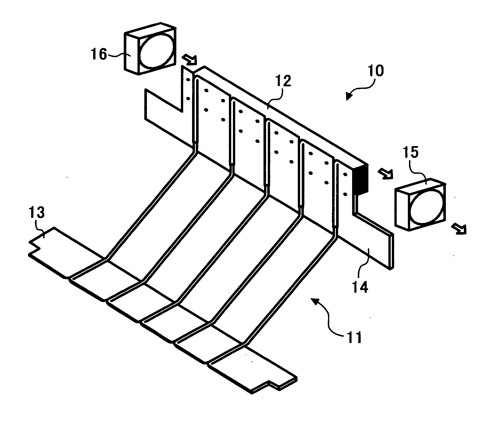
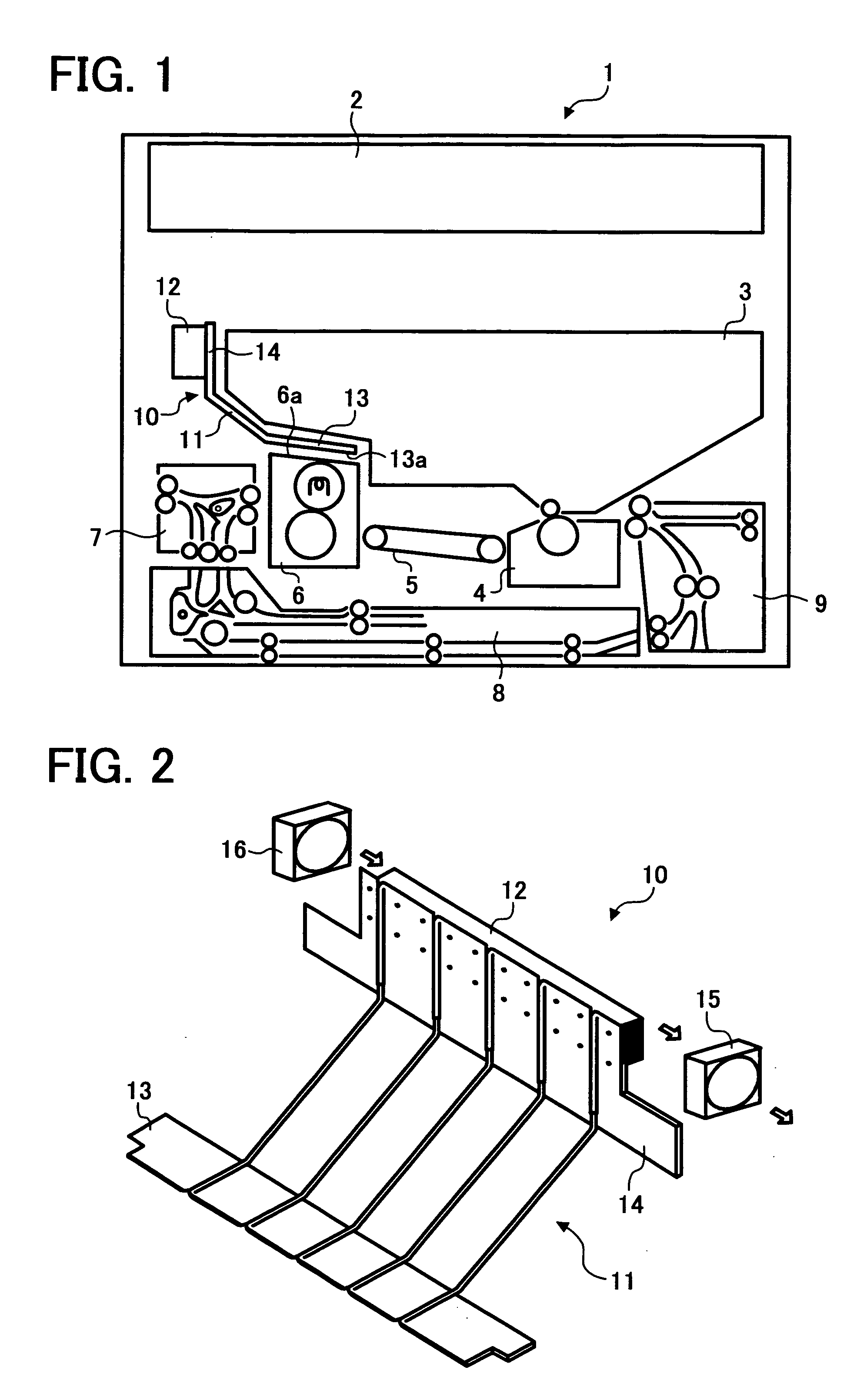
[0017] In describing preferred embodiments illustrated in the drawings, specific terminology is employed for the sake of clarity. However, the disclosure of this patent specification is not intended to be limited to the specific terminology so selected and it is to be understood that each specific element includes all technical equivalents that operate in a similar manner. Referring now to the drawings, wherein like reference numerals designate identical or corresponding parts throughout the several views, particularly to FIG. 1, an image forming apparatus 1 according to a preferred embodiment of the present invention is explained. The image forming apparatus 1 of FIG. 1 includes a scanner unit 2, an image forming unit 3, a transfer unit 4, a transfer belt 5, a fixing unit 6, an ejection unit 7, a duplex unit 8, a sheet feed unit 9, and a heat radiation unit 10.

[0018] The scanner 2 is arranged at an upper position of the image forming apparatus 1, and the image forming unit 3 is ar...


PUM


Abstract

An image forming apparatus includes an image forming mechanism, a transfer mechanism, a fixing mechanism, and a heat radiation mechanism. The image forming mechanism forms a toner image which is transferred by the transfer mechanism transfers onto a recording sheet and is fixed by the fixing mechanism. The heat radiation mechanism is disposed between the image forming and fixing mechanisms and radiates heat generated by the fixing mechanism. The heat radiation mechanism includes a heat receiving member, a heat radiating member, and a heat conduction member. The heat receiving member receives heat generated by the fixing mechanism. The heat radiating member radiates the heat received by the heat receiving member. The heat conduction member has a thermal conductive property to efficiently conduct the heat from the heat receiving member to the heat radiating member.

Description

BACKGROUND OF THE INVENTION [0001] 1. Field of the Invention [0002] The present invention relates to an image forming apparatus, and more particularly to an image forming apparatus which is capable of efficiently removing heated air undesirable to image reproduction. [0003] 2. Discussion of the Background [0004] In recent years, image forming apparatuses such as digital copiers, facsimile machines, printers, and the like have been provided with more functions according to the progress of enhancements in speed, digitalization, and colorization. Accordingly, as a side effect, an image forming apparatus is provided with an increased number of components which include those generating heat such as, for example, a polygon motor, a hard disc, etc. On the other hand, one of important requirements to general office machines is the downsizing. Therefore, an image forming apparatus is facing an issue that an increased heat amount is enclosed in a reduced space. SUMMARY OF THE INVENTION [0005]...

Claims


Application Information

Patent Timeline
IPC IPC(8): G03G21/20F25D9/00G03G15/00G03G15/20
CPCG03G15/20G03G21/206G03G21/203
Inventor IIJIMA, YASUAKITAKEHARA, KENICHITAKIGAWA, JUNYAUCHIDA, KEISUKE
Owner RICOH KK
Why Eureka
Try Eureka