
Foundation shock eliminator

a technology of foundation shock and eliminator, which is applied in the direction of building components, building types, constructions, etc., can solve the problems of adverse effects of shocks on the fabrication of electronic products, buildings collapsing or the influence of machines, and conventional foundation shock eliminators cannot diminish the effect of shocks transmitted through the ground, so as to reduce the effect of shock and efficiently dissipate shock energy

Inactive Publication Date: 2005-11-03
TSAI CHONG SHIEN
View PDF10 Cites 39 Cited by
  • Summary
  • Abstract
  • Description
  • Claims
  • Application Information

AI Technical Summary

Benefits of technology

[0014] The main objective of the invention is to provide a foundation shock eliminator with a damping element to efficiently dissipate shock energy to reduce the effect of shock on machines and buildings.
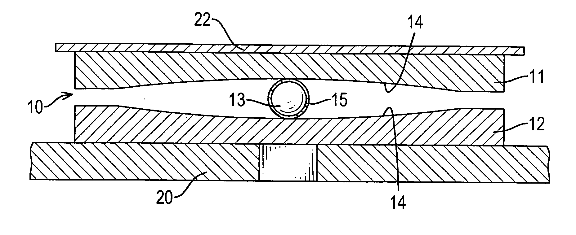
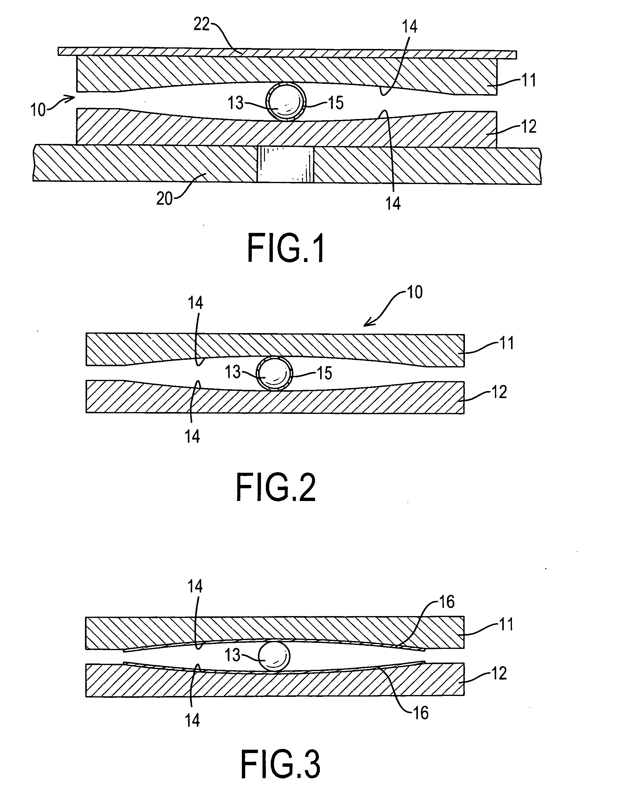
[0015] A foundation shock eliminator in accordance with the present invention to dissipate or eliminate shocks transmitted to buildings and machines includes an upper block, a lower stationary base, a roller and an energy damping coating. The upper block and the lower stationary base have respectively concave inner surfaces that face each other. The roller is mounted between the concave inner surfaces, rolls on the concave inner surface of the lower stationary base and supports the concave inner surface of the upper block. The energy damping coating dissipates shocks and is coated on at least one of the upper block, the lower stationary base and the roller. Consequently, the foundation shock eliminator will resist both vertical and horizontal shocks and diminish the effect of shock on the buildings and machines. The energy damping coating will keep the entire foundation shock eliminator from being unstable whether the foundation shock eliminator does or does not undergo shocks.

Problems solved by technology

Shocks will influence the fabrication of the electronic products adversely.
However, the conventional foundation shock eliminator cannot diminish the effect of shocks transmitted through the ground or the floor enough to keep the buildings from collapsing or the machines from being influenced adversely by the shocks.
Since the roller contacts each of the concave inner surfaces at a point and the concave inner surfaces are curved and slippery, the roller slips or rolls easily on the concave inner surface of the lower stationary base when no shock is applied to the foundation shock eliminator.
The entire foundation shock eliminator becomes unstable because of self-induced displacement of the roller by the machine or the building.
The conventional foundation shock eliminator cannot dissipate the shock energy efficiently so the undiminished shocks may damage the buildings or the machines.
Moreover, the conventional foundation shock eliminator only reduces the horizontal component of shocks and does nothing to reduce the vertical component of shocks.
Therefore, the applications and usage of the conventional foundation shock eliminator are restricted.

Method used


Image

  • Foundation shock eliminator
  • Foundation shock eliminator
  • Foundation shock eliminator

Examples


first embodiment

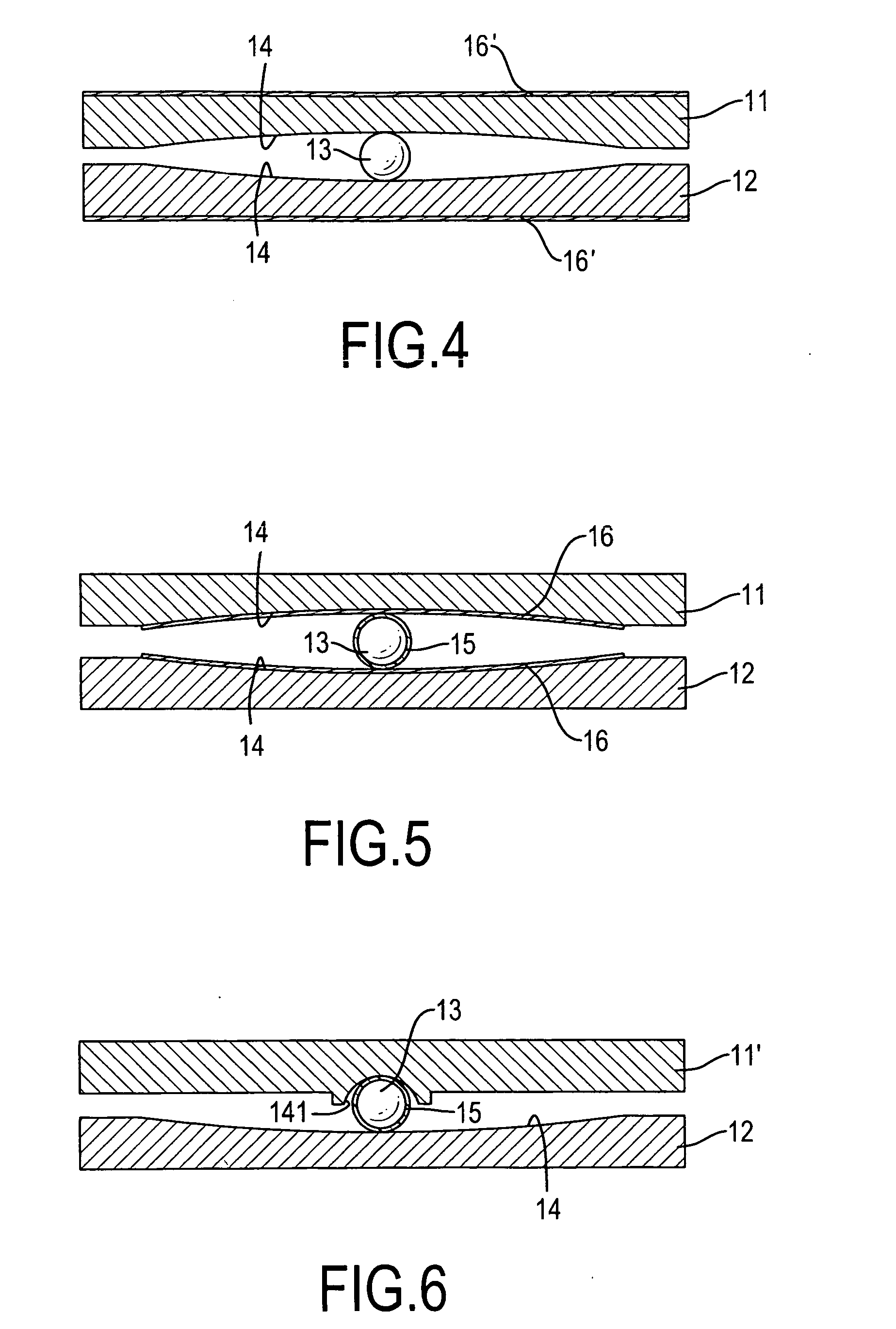
[0036] the energy damping coating can be viscoelastic material, rubber or other resilient material and is implemented as a roller coating (15). The roller coating (15) completely covers the roller (13). The roller coating (15) increases the damping of the entire foundation shock eliminator (10), which dissipates more shock energy than a conventional foundation shock eliminator.

second embodiment

[0037] With further reference to FIG. 3, the energy damping coating in accordance with the present invention is implemented as two surface coatings (16). The surface coatings (16) respectively cover the concave inner surfaces (14) of the upper block (11) and the lower stationary base (12). The roller (13) is movably mounted between the surface coatings (16).

[0038] With further reference to FIG. 4, a third embodiment of the energy damping coating in accordance with the present invention repositions the surface coatings (16) of the second embodiment of the energy damping coating to the outer surfaces respectively of the upper block (11) and the lower stationary base (12).

[0039] With further reference to FIG. 5, a fourth embodiment of the energy damping coating is a combination of the roller coating (15) in the first embodiment and the surface coatings (16) of the second embodiment of the energy damping coating. The roller coating (15) completely covers the roller (13). The surface co...

third embodiment

[0045] With further reference to FIGS. 11 and 12, a foundation shock eliminator in accordance with the present invention comprises a modified upper block (11″), a modified lower stationary base (12′), a roller (13), an energy damping coating and multiple restitution elements (17). The modified upper block (11″) has a hemispheric concave inner surface (141). The modified lower stationary base (12′) has a top surface (not numbered) and an upper wall (121). The upper wall (121) protrudes from the top surface and encloses an area (not numbered). The enclosed area has a central position (not numbered). The modified upper block (11″) is mounted movably inside the upper wall (121). The hemispheric concave inner surface (141) faces the modified lower stationary base (12′). The roller (13) is a ball or a cylindrical rod, is mounted rotatably in the hemispheric concave inner surface (141) and moves inside the enclosed area on the modified lower stationary base (12′). The energy damping coatin...


PUM


Abstract

A foundation shock eliminator for buildings or machines to dissipate or eliminate shock energy includes an upper block, a lower stationary base, a roller and an energy damping coating. The upper block and the lower stationary base have respectively a concave inner surface. The concave inner surfaces face each other. The roller is mounted between the concave inner surfaces. The energy damping coating dissipates the shock energy and is covers at least one of the surfaces of the upper block, the lower stationary base and the roller. Consequently, the foundation shock eliminator will aid the buildings or the machines to resist both vertical and horizontal shocks and diminish the shock effects to the buildings or machines. The energy damping coating will keep the entire foundation shock eliminator from being unstable whether or the foundation shock eliminator is subjected to shocks.

Description

BACKGROUND OF THE INVENTION [0001] 1. Field of the Invention [0002] The present invention relates to a foundation shock eliminator, and more particularly to a foundation shock eliminator that introduces a moveable, passive damping element to dissipate shock energy efficiently. [0003] 2. Description of Related Art [0004] Vibration control and shock reduction are fundamental concerns in the construction of buildings, machines and industrial manufacturing instruments. Diminishing the effect of shocks on objects is achieved primarily by isolating the shocks or absorbing the shocks. [0005] In electronic industries, manufacturing electronic products such as semiconductor wafers and integrated circuits uses sophisticated processes that must be kept stable. Shocks will influence the fabrication of the electronic products adversely. Therefore, reducing the effect of shock on manufacturing machines in electronic industries is always an important concern. [0006] A conventional foundation shock...

Claims


Application Information

Patent Timeline
IPC IPC(8): E04B1/98E04H9/02
CPCE04H9/023
Inventor TSAI, CHONG-SHIEN
Owner TSAI CHONG SHIEN
Learn More