Phase selectable divider circuit

a divider circuit and phase selectable technology, applied in the field of divider circuits, can solve the problems of limiting the maximum possible speed of the divider circuit in certain applications, and being unsuitable for certain applications

Active Publication Date: 2005-11-03
SKYWORKS SOLUTIONS INC
View PDF11 Cites 25 Cited by
  • Summary
  • Abstract
  • Description
  • Claims
  • Application Information

AI Technical Summary

Problems solved by technology

Several aspects of the divider circuit illustrated in FIG. 1 may make it undesirable for certain applications.
The feedback loop formed by the first-stag

Method used


Image

  • Phase selectable divider circuit
  • Phase selectable divider circuit
  • Phase selectable divider circuit

Examples


Embodiment Construction

)

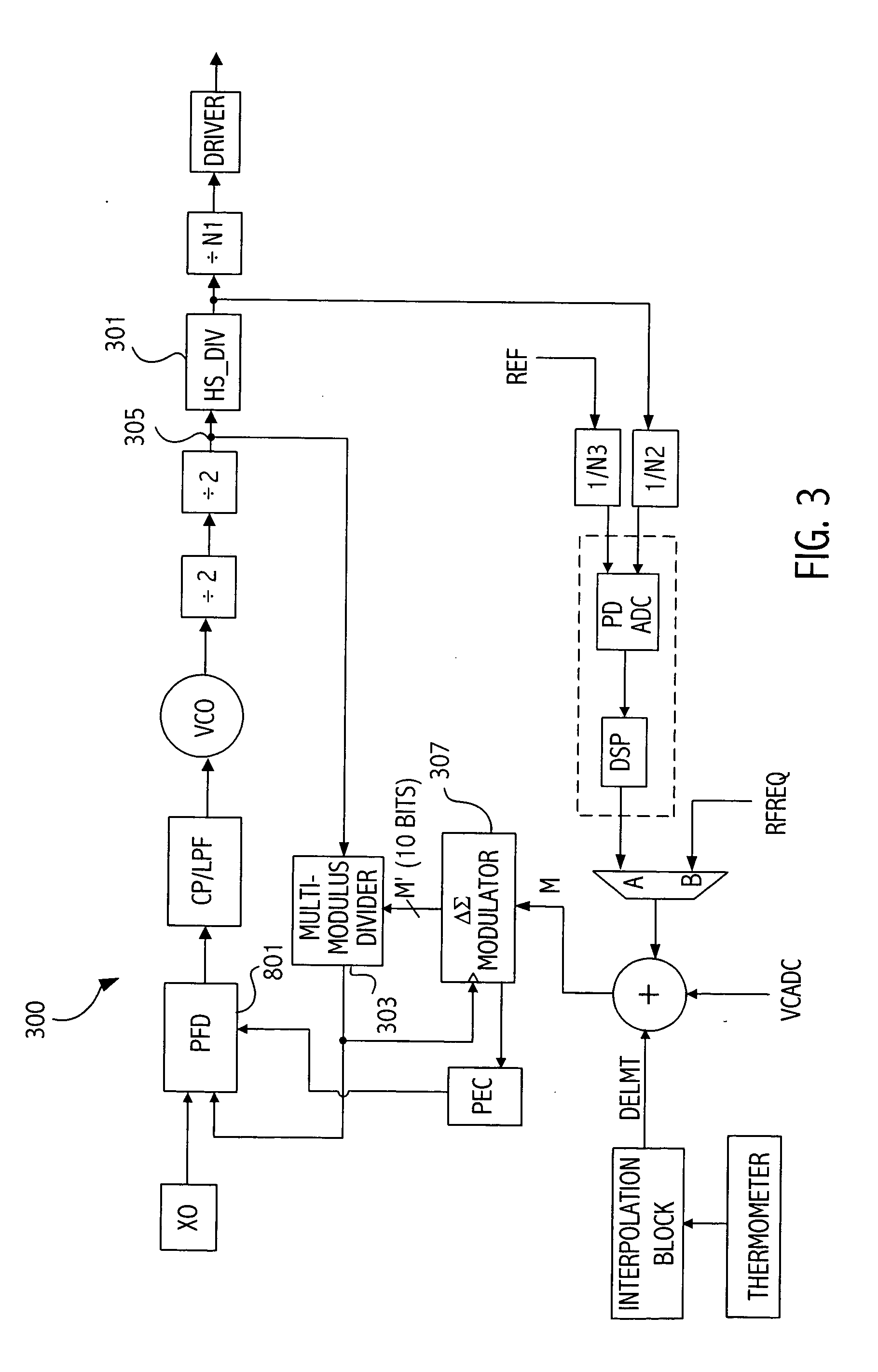
[0047] Referring to FIG. 3 a block diagram illustrates an exemplary architecture 300 that may utilize divider circuits incorporating embodiments of the invention in, e.g., divider circuits 301 and 303. A divider circuit according to an embodiment of the invention is utilized to divide a clock signal supplied on node 305. In the exemplary embodiment illustrated in FIG. 3, the divider circuits 301 and 303 receive a clock signal supplied at node 305 that is approximately 2.5 GHz.

[0048] Before describing divider circuit 303 in more detail in a specific implementation, a more general discussion of a phase selectable divider circuit will be provided. Referring now to FIG. 4 illustrated is a block diagram of a divider circuit 400 according to an embodiment of the invention. Eight clock signals P0-P7 are supplied to selector circuit 401. In the illustrated embodiment, selector circuit 401 is implemented as a multiplexer. A three bit control signal 403 supplied from register 405 selects wh...


PUM


Abstract

A phase selectable divider circuit includes a select circuit receiving a plurality of signals having a common frequency and a different phase. One of the plurality of signals, having a first phase, is selected as a selector circuit output signal. A first value corresponding to the first phase is summed with a second value corresponding to a phase offset from the first phase to generate a sum indicative thereof. That sum is used to select a second one of the signals having a second phase as the next selector circuit output signal. As successive sums are generated, a pulse train is supplied by selector circuit having a desired frequency.

Description

CROSS-REFERENCE TO RELATED APPLICATION(S) [0001] This application claims benefit to a provisional application 60 / 567,479, under 35 U.S.C. § 119(e), naming Axel Thomsen et al., as inventors, entitled “METHOD AND APPARATUS FOR A PROGRAMMABLE CLOCK SOURCE GENERATING A WIDE RANGE OF OUTPUT FREQUENCIES”, filed May 3, 2004.BACKGROUND [0002] 1. Field of the Invention [0003] This application relates to divider circuits and more particularly to programmable divider circuits useful for dividing high speed signals. [0004] 2. Description of the Related Art [0005] Many applications use divider circuits to divide high speed clock signals. In order to provide flexibility, programmable divider circuits may be preferred in some applications. Several approaches for such programmable divider circuits are known in the art. For example, FIG. 1 illustrates a programmable divider based on a conventional dual modulus prescalar. The output frequency fout=finR⁡(P+1)+(Q-R)⁢P=finQP+R. Several aspects of the d...

Claims


Application Information

Patent Timeline
IPC IPC(8): H03K23/66H03L7/00H03L7/193H03L7/197
CPCH03K23/66H03L7/1976H03L7/193
Inventor SUN, LIZHONGPASTORELLO, DOUGLAS F.JUHN, RICHARD J.THOMSEN, AXEL
Owner SKYWORKS SOLUTIONS INC
Why Eureka
Try Eureka