
Adjustable display stereoscope

Inactive Publication Date: 2005-11-03
LA WILLIAM H T
View PDF4 Cites 11 Cited by
  • Summary
  • Abstract
  • Description
  • Claims
  • Application Information

AI Technical Summary

Benefits of technology

[0016] Accordingly, several objects and advantages of the present invention are to provide:
[0017] (a) a self-standing display system for stereoscopic visual content that securely holds, supports, protects, and exhibits the content material, and is adapted for stable upright setting on a horizontal surface, or optional mounting on a vertical or slanted surface;
[0018] (b) an aesthetically pleasing stereoscopic display that has a clean, uncluttered, stylish and modern appearance, is suitable for use as a decorative object, and has wide appeal for people of various ages and interests in a home or place of business;
[0019]

Problems solved by technology

There are, however, serious limitations associated with this method of enjoying a stereo picture.
First, many people find it difficult or impossible to maintain parallel lines of sight while focusing on a near object.
Third, since our eyes cannot be made to diverge to any significant extent, a stereo pair configured for such use is necessarily limited to a maximum field separation substantially equal to the interpupillary distance, approximately 6.5 cm (2.5 in).
Though practicable, free-viewing is therefore unsatisfying and fails to exploit the full potential of third dimensional representation possible with a pair of 2-D images.
While simple and inexpensive, this handheld device suffers from a lack of steady support of the stereograph for alignment with the eyepiece, rendering its operation difficult for many users.
This apparatus uses lens fragments of a smaller size to limit the field of view and eliminate the need for a septum, but still does not adequately address the problem of securely squaring the viewer and the view.
This device is advantageous for viewing either 3-D images displayed in a book or stereoscopic pictures lying flat on a surface, with a simple provision for adjusting interocular distance, but is not adapted for holding a card in position.
However, this device is presented and regarded as a child's toy, and there is no accessible way for a user to make her own stereo slides to view with it.
Moreover, the available images cannot be enjoyed independently of the viewer.
Some improvements emphasize the incorporation of a large amount of content in the fashion of a book, such as U.S. Pat. No. 2,616,333 to Tinker, 1952 Nov. 4; U.S. Pat. No. 5,204,776 to Seamans and Harvey, 1993 Apr. 20; and U.S. Pat. No. 6,456,433 to Jones, 2002 Sep. 24. These specialized devices have relatively complex designs and require multiple steps in their manufacture.
However, they lack adjustment capability and their general appearance matches their low cost.
While this technique incrementally facilitates stereo viewing, it interferes with the visibility of the picture with respect to a bystanding observer, and detracts from the display value of the stereoscope.
However, adjustability is absent and the instrument has to be partially disassembled in order to change the view.
A limitation common to septated stereoscopes is the difficulty in evenly lighting the stereograph.
Aside from the ViewMaster®, no other stereoscope is readily available to the public.
There exists no accessible way for the average person to engage in creating, viewing and exhibiting quality stereographs of friends and family.
Even though the science is well-known, the art has not kept up with advancing technology and evolving tastes.

Method used


Image

  • Adjustable display stereoscope
  • Adjustable display stereoscope
  • Adjustable display stereoscope

Examples


Embodiment Construction

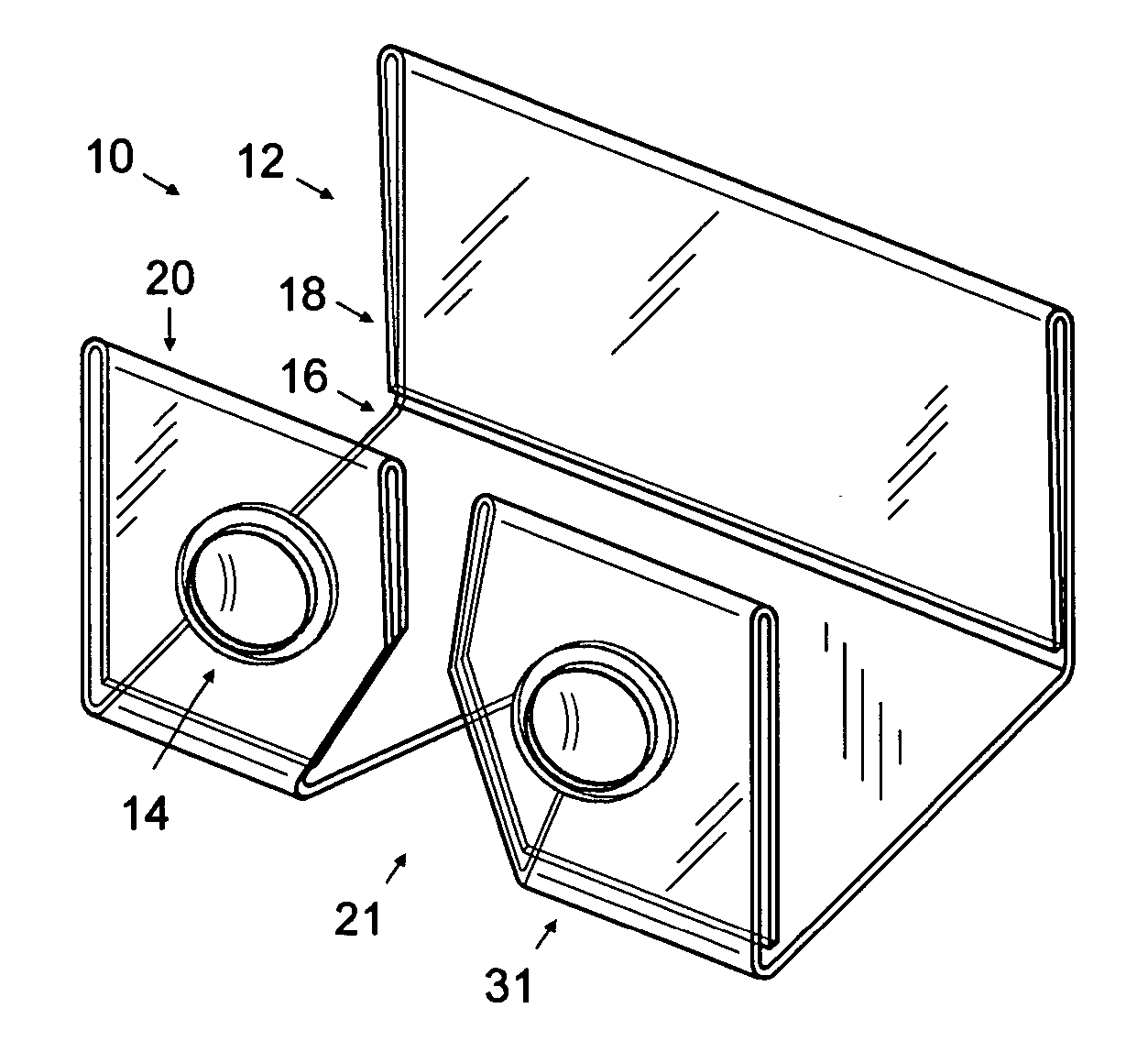
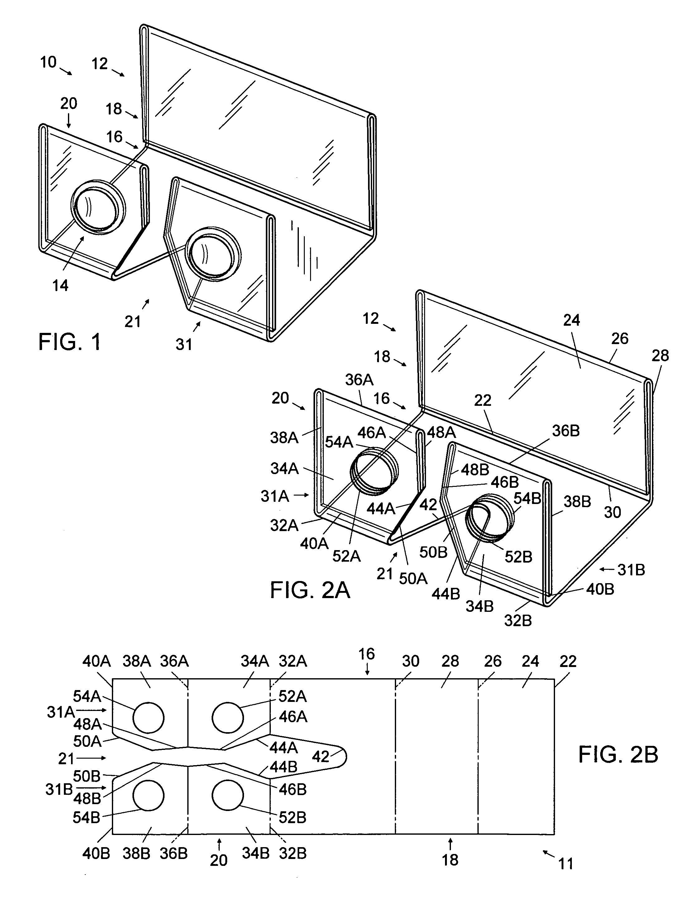
[0088]FIG. 1 shows the preferred embodiment of the adjustable display stereoscope 10 that comprises a body 12 and a pair of lenses 14. Body 12 is fabricated from a single sheet of thin transparent acrylic plastic of approximately 1.6 mm in thickness, cut in the appropriate places and heat-formed into a base section 16, a picture holder section 18 and a lens holder section 20. Median slot 21 divides the lens holder section and part of the base section into two lens support arms 31.

[0089]FIG. 2A shows body 12 without the lenses, and FIG. 2B shows cut plastic sheet 11 from which the body is fabricated by forming four folds. At the center of body 12 is base 16 which is attached on one end to picture holder 18 through fold 30. Picture holder 18 is comprised of picture holder panel 28 and picture holder flap 24, which are connected through fold 26 and end in edge 22. At the other end of base 16, nose slot 42 divides the base into two lateral members which lead through folds 32A and 32B t...


PUM


Abstract

A stereoscopic display system (10) comprising a pair of convergent lenses (14) and a sheet of resilient, transparent material (12) formed into a picture holder (18) and a lens holder (20) joined by a base (16) that holds them erect and parallel for viewing a stereoscopic image pair mounted in the picture holder through the lenses mounted in the lens holder. A median slot (21) extending through the lens holder into an adjacent portion of the base divides these sections into two lens support arms (31) and provides an intervening space shaped to accommodate the viewer's nose and to maintain a clearance space for the resilient approximation of the lens support arms. Adjustments for focus, diopter, interpupillary distance, and stereofield separation and vertical alignment, are made by flexing the lens support arms collectively and differentially in longitudinal and transverse directions. The picture holder is adapted to durably or transiently hold stereograms of various sizes and formats, in the form of prints, transparencies or slides, LCDs or other thin image support media. A second picture can be displayed on the reverse side of the picture holder. The lens holder can accept replacement optics for optics for customization to the user's vision requirements and can be adapted for durable setting of interocular distance.

Description

CROSS REFERENCE TO RELATED APPLICATIONS [0001] Not Applicable FEDERALLY SPONSORED RESEARCH [0002] Not Applicable SEQUENCE LISTING OR PROGRAM Not Applicable BACKGROUND OF THE INVENTION [0003] 1. Field of Invention [0004] This invention relates to stereoscopes, and more specifically to stereoscopes that include a twin-lens eyepiece connected to a holder for a stereogram. This invention applies to stereograms that are composed of two adjacent images, or fields, each corresponding to one eye. A stereogram is understood as a stereoscopic image generated by any method, and a stereograph more specifically as a photographic stereogram, these two words being used interchangeably herein. [0005] 2. Description of Prior Art [0006] Our perception of depth in our surroundings comes from many visual cues, an important one being the parallax of the two similar but non-identical images seen by our two eyes. A stereograph presents two views of a scene that incorporate a shift in viewpoint parallel to...

Claims


Application Information

Patent Timeline
IPC IPC(8): G03B23/12G03B25/00G03B35/00G03B35/18
CPCG03B35/18G03B23/12
Inventor LA, WILLIAM H.T.
Owner LA WILLIAM H T
Learn More