Data erasure apparatus, data erasure method and method for writing servo patterns on recording disk

a data eraser and data technology, applied in the field of data erasers, can solve the problems of further stopping the rotation, insufficient data on the inner side, and deteriorating the characteristics of the spindle motor, so as to achieve efficient and reliable data erase, reliably eliminate the magnetic step, and eliminate the effect of the magnetic step

Inactive Publication Date: 2005-11-03
WESTERN DIGITAL TECH INC
View PDF16 Cites 18 Cited by
  • Summary
  • Abstract
  • Description
  • Claims
  • Application Information

AI Technical Summary

Benefits of technology

[0008] The magnetic disk is rotated at a predetermined speed by the spindle motor fixed to the base. Several components of the spindle motor are made of magnetic materials or magnets and therefore affected greatly by the external magnetic field. In particular, taking calmness and durability into consideration, many hard disk drives these days employ a fluid dynamic bearing motor instead of a ball bearing motor. Due to its structure, the fluid dynamic bearing motor is more apt to be affected by external magnetic field than the ball bearing motor. If a strong magnetic field is applied in order to erase the data on a magnetic disk, this may deteriorate characteristics of the spindle motor and further stop the rotation.
[0024] According to the present invention, data on a magnetic disk can be erased effectively.

Problems solved by technology

If a strong magnetic field is applied in order to erase the data on a magnetic disk, this may deteriorate characteristics of the spindle motor and further stop the rotation.
However, if only the outer side of the magnetic disk is partly inserted between the permanent magnets, data on the inner side cannot be erased sufficiently since only a weak magnetic field acts on the inner side of the magnetic disk although a sufficiently strong magnetic field can be applied to the outer side.

Method used


Image

  • Data erasure apparatus, data erasure method and method for writing servo patterns on recording disk
  • Data erasure apparatus, data erasure method and method for writing servo patterns on recording disk
  • Data erasure apparatus, data erasure method and method for writing servo patterns on recording disk

Examples


embodiment 1

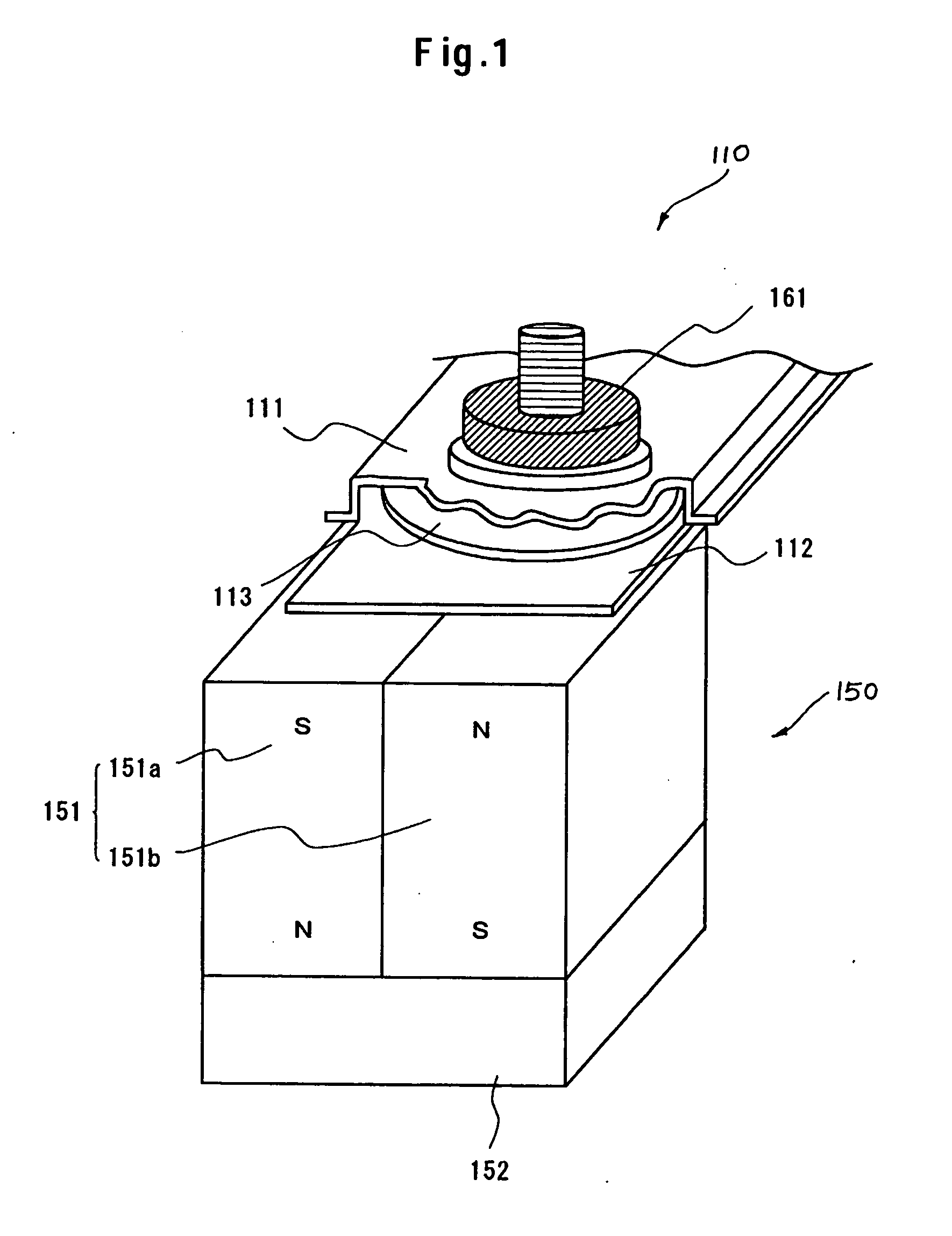
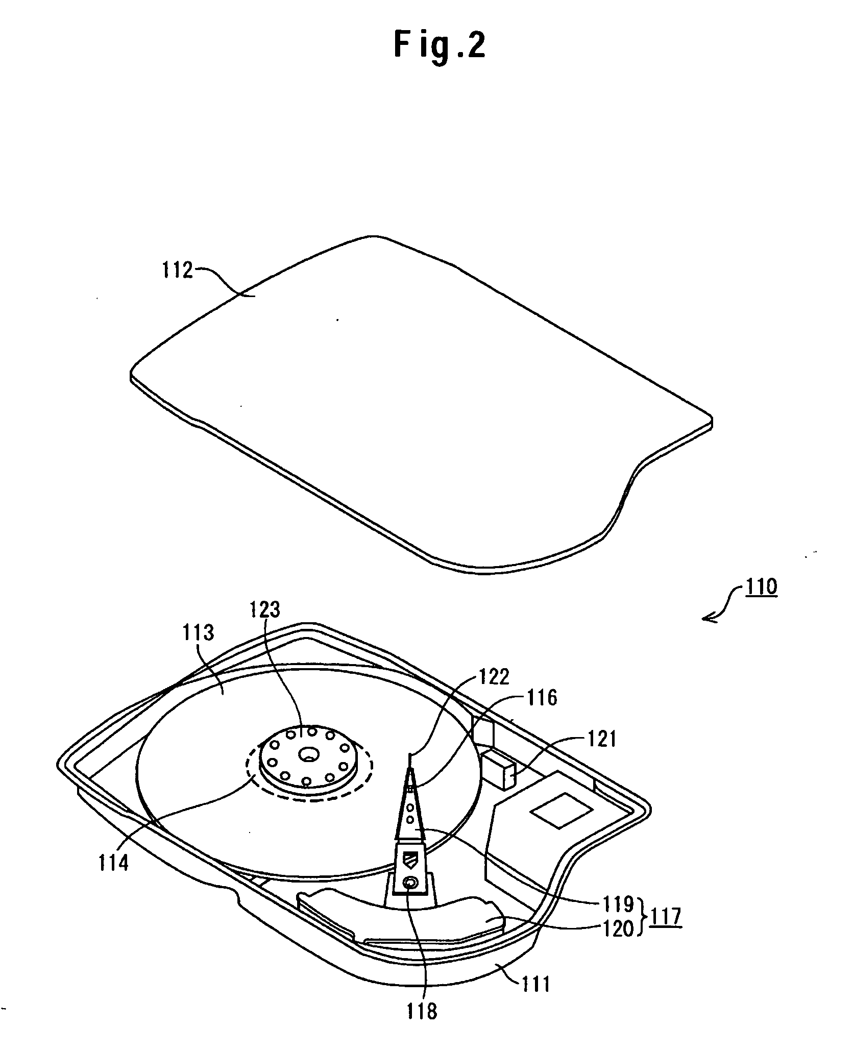
[0040]FIG. 1 is provided to explain the principle of data erasure by this embodiment for a hard disk drive (HDD). AN HDD 110 comprises a boxy base 111 having an opening; and a top cover plate 112 to cover the opening of the base 111. The base 111 and the top cover 112 are integrated via a gasket (not shown) of fluorocarbon rubber or the like to form a sealed disk enclosure which accommodates the components of the hard disk drive 110.

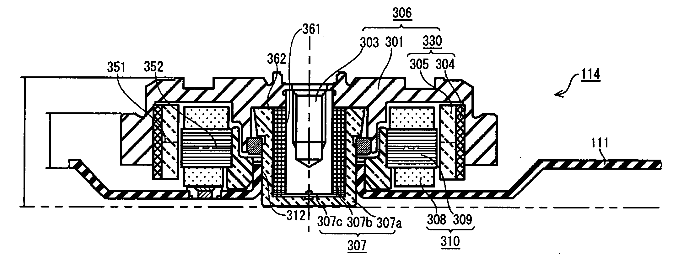
[0041] In FIG. 1, the base 111 is partly cut out to illustrate and explain the internal structure. As shown in FIG. 1, the HDD 110 has a data recording magnetic disk 113 in the enclosure. The spindle motor (not shown in FIG. 1) to rotate the magnetic disk 113 in this HDD 110 has a fluid dynamic bearing structure. The configuration of the HDD 110 and that of the spindle motor will be described later.

[0042] The reference numeral 150 denotes a data erasure apparatus to erase magnetic data stored on the magnetic disk 113. In the interest of explanation, FI...

embodiment 2

[0072] As mentioned above, use of the erasing permanent magnet 151 allows efficient and quick data erasure by magnetizing the magnetic disk 113 in a single direction. If the back yoke 161 is not used, however, it is necessary to reduce the overlap between the erasing permanent magnet 151 and the magnetic disk 113 in order to prevent the fluid dynamic bearing spindle motor 114 from stopping. This can prevent the spindle motor 14 from stopping by reducing the influence of the magnetic force of the erasing permanent magnet 151 which attracts the rotor 306 and top clamp 123.

[0073] However, if the erasing permanent magnet 151 is overlapped with only the outer data storage area of the magnetic disk 113 and not overlapped with the inner storage area, the data in the inner storage area cannot be erased although the data in the outer data storage area can be erased. Use of the back yoke 161 yet has a problem that if the magnetic force of the erasing permanent magnet 151 is large, the data i...


PUM

PropertyMeasurementUnit
external magnetic fieldaaaaaaaaaa
magnetic forceaaaaaaaaaa
cylindrical shapeaaaaaaaaaa

Abstract

Embodiments of the invention prevent a spindle motor from stopping rotation while data on a magnetic disk is being erased by using a permanent magnet. In one embodiment, data in the whole area of the magnetic disk is erased as a consequence of the magnetic disk rotating in the magnetic field of the permanent magnet located so as to face a part of the magnetic disk. A back yoke is located so as to face a base. The back yoke gives a magnetic force to the spindle motor in the opposite direction of the magnetic force of the erasing permanent magnet so that the fluid dynamic bearing spindle motor can retain the rotation as required without stopping rotation.

Description

CROSS-REFERENCES TO RELATED APPLICATIONS [0001] This application claims priority from Japanese Patent Application No. JP 2004-134431, filed Apr. 28, 2004, the entire disclosure of which is incorporated herein by reference. BACKGROUND OF THE INVENTION [0002] The present invention relates to a data erasure apparatus, a data erasure method and a method for writing servo patterns on a recording disk. [0003] A typical hard disk drive (HDD) comprises a magnetic disk, a spindle motor to drive the magnetic disk to rotate, a magnetic head to write / read data to / from the magnetic disk, and others. The HDD has an enclosure case which accommodates the components. The enclosure case is generally made of a boxy base having an opening and a top cover plate covering the opening of the base. [0004] Assembling of the disk device is completed when the opening of the base is covered by the top cover after the components are mounted in the base. After the assembly is completed, servo patterns are written...

Claims


Application Information

Patent Timeline
Patent Type & Authority Applications(United States)
IPC IPC(8): G11B5/024G11B5/325G11B5/596G11B19/20G11B21/10
CPCG11B5/0245G11B19/20G11B5/59633G11B5/325G11B5/024
Inventor KITAMURA, MITSURUKATOH, MASAHIKOTAMURA, HITOSHIUCHIYAMA, HIROAKIMURAYAMA, MASASHIIKEDA, MIGIFUMISASAKI, KAZUOWATABE, SHIGEKI
Owner WESTERN DIGITAL TECH INC
Why Eureka
Try Eureka