Pilot designing method in an uplink OFDMA system

a pilot design and uplink technology, applied in the field of mobile communication systems, can solve the problems of degradation of channel estimation performance, reference channel estimation is not available for interpolation, and degradation of whole data detection performance, and achieve the effect of maximizing channel estimation efficiency

Inactive Publication Date: 2005-11-03
SAMSUNG ELECTRONICS CO LTD +1
View PDF9 Cites 69 Cited by
  • Summary
  • Abstract
  • Description
  • Claims
  • Application Information

AI Technical Summary

Benefits of technology

[0011] An object of the present invention is to substantially solve at least the above problems and/or disadvantages and to provide at least the advantages below. Accordingly, an object of the present invent

Problems solved by technology

The limit of the pilot information which is available to each user degrades channel estimation performance.
However, at the boundary A between the transport blocks of the two users, a pilot subcarrier is nonexistent for user #1 on the outside of his transport block and thus a reference channel estimate is not available for interpolation.
As a result, a channel estimation erro

Method used


Image

  • Pilot designing method in an uplink OFDMA system
  • Pilot designing method in an uplink OFDMA system
  • Pilot designing method in an uplink OFDMA system

Examples


second embodiment

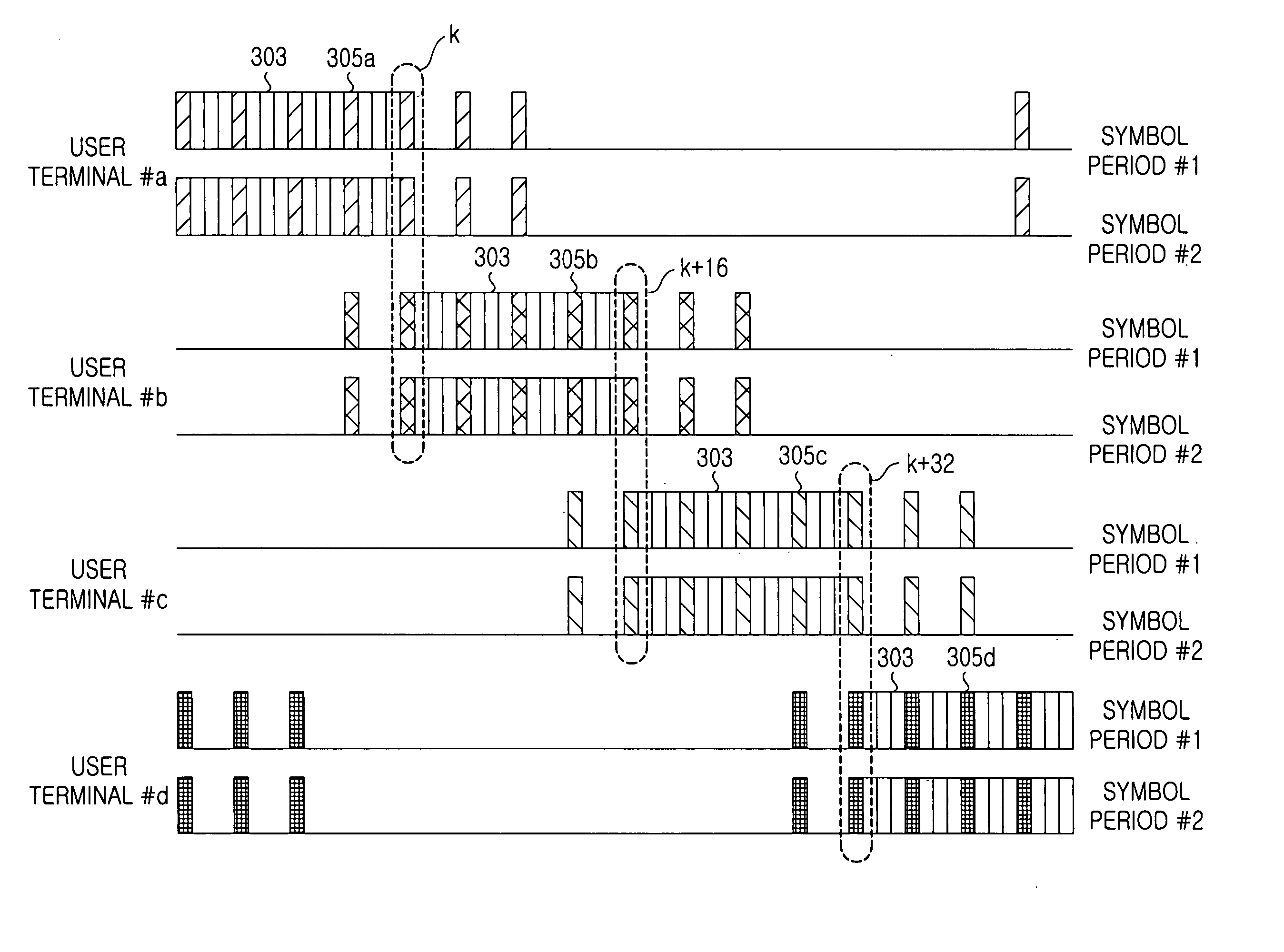
[0060]FIG. 4 is a conceptual view illustrating a pilot designing method according to the present invention.

first embodiment

[0061] As in the present invention, it is assumed that there are four user terminals allocated to adjacent transport blocks, each transport block includes 16 subcarriers for two successive symbol periods, and the channels do not change for the symbol periods.

[0062] Referring to FIG. 4, user terminal #a, user terminal #b, user terminal #c, and user terminal #d are each allocated a transport block including data subcarriers 403 which are not overlapped with data subcarriers 403 of the other user terminals in two symbol periods.

[0063] In symbol period #1, user terminal #a uses a pilot subcarrier which is located at a pilot subcarrier position #k which is allocated to user terminal #b as its own, and user terminal #c uses a pilot subcarrier which is located at a pilot subcarrier position #(k+32)th which is allocated to user terminal #d as its own.

[0064] In symbol period #2, user terminal #b uses a pilot subcarrier which is located at a pilot subcarrier position #(k+16)th which is allo...

third embodiment

[0067]FIG. 5 is a conceptual view illustrating a pilot designing method according to the present invention.

[0068] For notational simplicity, it is assumed that there are two user terminals allocated to adjacent transport blocks, and each transport block includes 2 subcarriers for 28 successive symbol periods.

[0069] Referring to FIG. 5, user terminal #a and user terminal #b are allocated pilot symbol periods 505a and 505b respectively, which are intermittent with respect to data symbol periods 503. At the end time area of the transport block of user terminal #a, there is no pilot symbol period. Hence, user terminal #a shares a pilot symbol period #k which is allocated to user terminal #b. User terminals #a and #b use orthogonal pilot patterns [11] and [1−1].


PUM


Abstract

A pilot designing method in an uplink OFDMA system is provided. In the uplink OFDMA system, communications are carried out in a frame divided into time-frequency lattices, and each time-frequency lattice includes a plurality of data symbol periods and a plurality of pilot symbol periods intermittently arranged with respect to the data symbol periods. The frame is divided into a plurality of blocks. The blocks are allocated to the terminals. A predetermined allocated pilot time-frequency lattice is shared between adjacent terminals.

Description

PRIORITY [0001] This application claims priority under 35 U.S.C. § 119 to an application entitled “Pilot Designing Method in an Uplink OFDMA System” filed in the Korean Intellectual Property Office on Mar. 11, 2004 and Nov. 26, 2004 and assigned Serial Nos. 2004-16552 and 98174-2004, respectively, the contents each of which are incorporated herein by reference. BACKGROUND OF THE INVENTION [0002] 1. Field of the Invention [0003] The present invention relates generally to a mobile communication system, and in particular, to a pilot designing method for channel estimation on the uplink in an orthogonal frequency division multiple access (OFDMA) system. [0004] 2. Description of the Related Art [0005] High-speed, high-quality data transmission is required for next-generation mobile communications to provide a variety of multimedia services with improved quality. [0006] Orthogonal Frequency Division Multiplexing (OFDM), on which OFDMA is based, boasts high-speed communication due to low e...

Claims


Application Information

Patent Timeline
IPC IPC(8): H04J11/00H04L27/26
CPCH04L5/0023H04L5/0048H04L25/0232H04L25/0226H04L25/0204H04L5/0007H04L25/0224
Inventor JUNG, YOUNG-HOCHUNG, JAE-HAKHWANG, CHAN-SOONAM, SEUNG-HOONLEE, YONG-HOONPARK, HONG-SUN
Owner SAMSUNG ELECTRONICS CO LTD
Why Eureka
Try Eureka