Performance monitoring based on optical autocorrelation

a performance monitoring and autocorrelation technology, applied in the field of optical communication systems, can solve the problems of insufficient application of optical performance monitoring techniques, typically requires high-speed electronics,

Active Publication Date: 2005-11-03
ALCATEL-LUCENT USA INC +1
View PDF13 Cites 14 Cited by
  • Summary
  • Abstract
  • Description
  • Claims
  • Application Information

AI Technical Summary

Benefits of technology

[0007] Problems in the prior art are addressed, in accordance with the principles of the present invention, by an optical performance monitor (OPM) adapted to (i) sample an autocorrelation function corresponding to an optical signal transmitted in an optical network and (ii) based on the sampling, characterize two or more impairments concurrently present in the optical signal. In one embodiment, the OPM has an optical autocorrelator (OAC) coupled to a signal processor (SP). The OAC receives the optical signal from the network, generates two or more samples of its autocorrelation function, and applies said samples to the SP. The SP processes the samples and generates two or more signal metrics. Based on the signal metrics and reference data corresponding to the impairments, the SP then obtains a measure of each of the impairments. For example, when two concurrently present impairments are optical noise and chromatic dispersion, the reference data provide two three-dimensional reference surfaces, each surface representing the corresponding impairment as a function of the signal metrics. A current value of each impairment is determined from the point on the corresponding reference surface having the current values of the signal metrics as coordinates. Advantageously, both an optical signal-to-noise ratio (OSNR) value and a value of chromatic dispersion can unambiguously be assigned to the optical signal based on the autocorrelation and reference data. An OPM of the invention may be used to observe and / or adjust the performance of a communication link.
[0008] According to one embodiment, the present invention is an apparatus for performance monitoring in a communication system, the apparatus comprising: (a) an OAC adapted to receive an optical signal from the communication system and to generate two or more samples of an autocorrelation function corresponding to the optical signal; and (b) an SP coupled to the OAC and adapted to characterize two or more impairments concurrently present in the optical signal based on the two or more samples.
[0009] According to another embodiment, the present invention is a method for monitoring performance in a communication system, the method comprising: (A) generating two or more samples of an optical autocorrelation function corresponding to an optical signal of the communication system; and (B) characterizing two or more impairments concurrently present in the optical signal based on the two or more samples.

Problems solved by technology

However, one disadvantage of this method is that it typically requires high-speed electronics.
While nonlinear optical techniques are particularly suitable for optical performance monitoring, practical applications of such techniques to optical performance monitoring are not yet sufficiently developed.

Method used


Image

  • Performance monitoring based on optical autocorrelation
  • Performance monitoring based on optical autocorrelation
  • Performance monitoring based on optical autocorrelation

Examples


Embodiment Construction

[0018] Reference herein to “one embodiment” or “an embodiment” means that a particular feature, structure, or characteristic described in connection with the embodiment can be included in at least one embodiment of the invention. The appearances of the phrase “in one embodiment” in various places in the specification are not necessarily all referring to the same embodiment, nor are separate or alternative embodiments mutually exclusive of other embodiments.

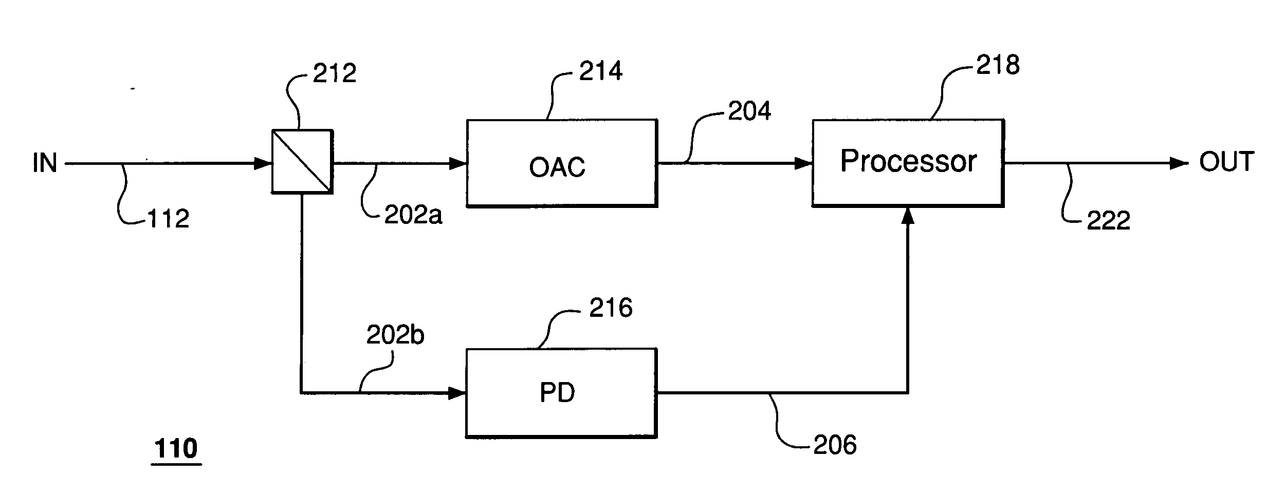
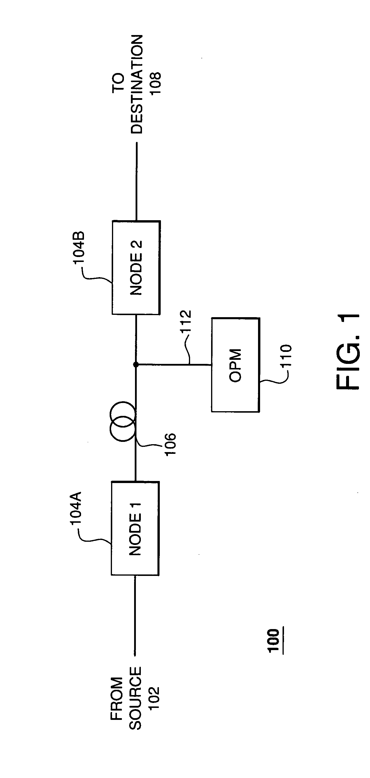
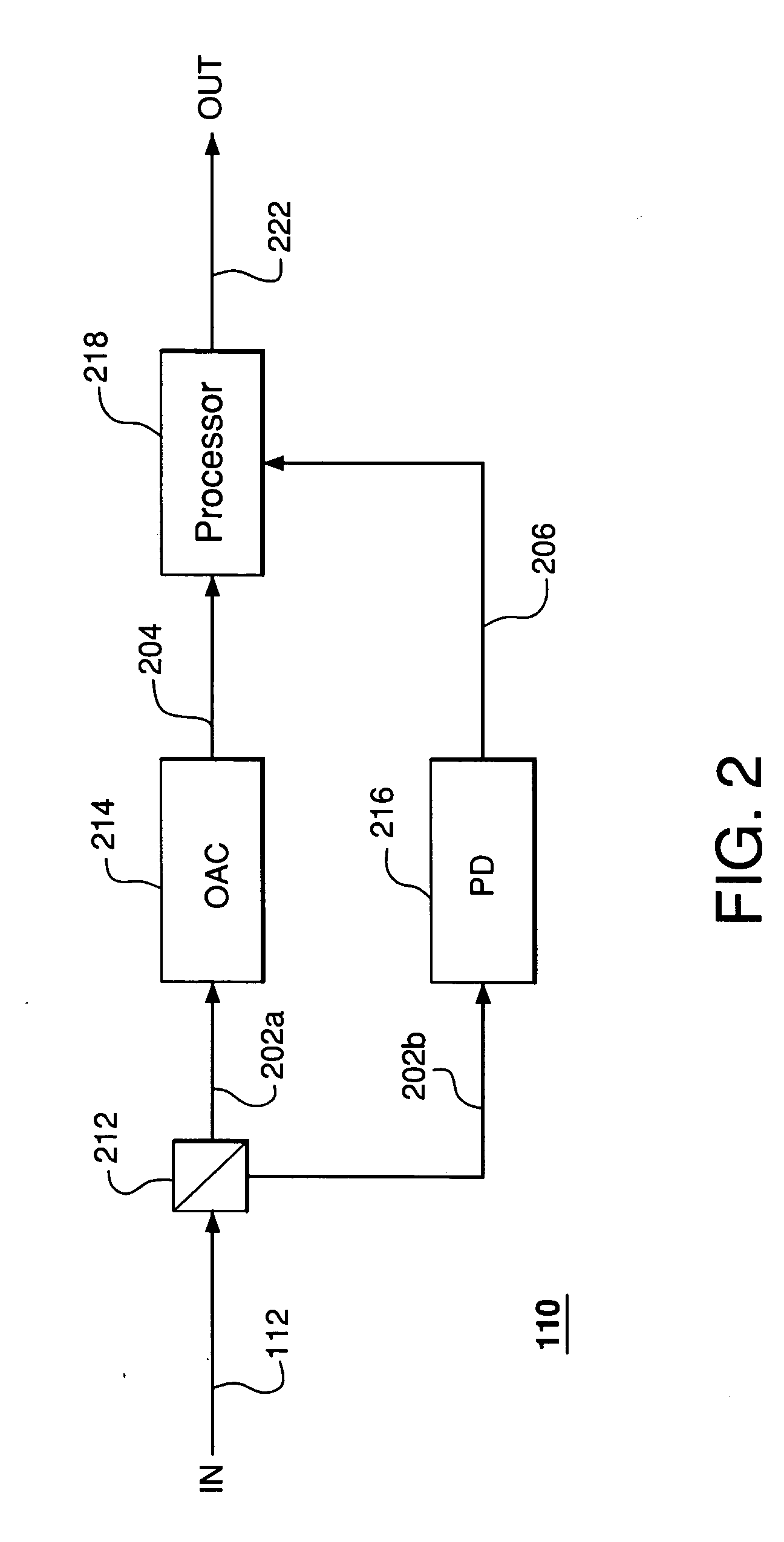
[0019]FIG. 1 illustrates a fiber optic network 100, which utilizes an optical performance monitor (OPM) 110 according to one embodiment of the present invention. Network 100 is configured to carry optical signals modulated with data from a source node 102 to a destination node 108 via a plurality of intermediate nodes 104. A long-haul, metro, or access optical transmission link, such as link 106, may connect a pair of nodes, such as intermediate nodes 104A and 104B shown in FIG. 1. Link 106 may include optical amplifiers (not sho...


PUM


Abstract

An optical performance monitor (OPM) adapted to (i) sample an autocorrelation function corresponding to an optical signal transmitted in an optical network and (ii) based on the sampling, characterize two or more impairments concurrently present in the optical signal. In one embodiment, the OPM has an optical autocorrelator (OAC) coupled to a signal processor (SP). The OAC receives the optical signal from the network, generates two or more samples of its autocorrelation function, and applies said samples to the SP. The SP processes the samples and generates two or more signal metrics. Based on the signal metrics and reference data corresponding to the impairments, the SP then obtains a measure of each of the impairments.

Description

CROSS-REFERENCE TO RELATED APPLICATIONS [0001] The subject matter of this application is related to that of U.S. patent application Ser. No. 10 / 109,623, filed Mar. 28, 2002, and entitled “Performance Monitoring in an Optical Communication System,” the teachings of which are incorporated herein by reference.BACKGROUND OF THE INVENTION [0002] 1. Field of the Invention [0003] The present invention relates to optical communication systems and, more specifically, to monitoring the performance of such systems. [0004] 2. Description of the Related Art [0005] Fiber optic networks are widely used for data transmission in modern communication systems. Due to increasing data traffic volumes, monitoring and management of networks become increasingly important. For example, such monitoring may include a measurement at a particular point in the network of the quality of an optical signal corresponding to one or more optical communication channels. The optical signal may be analyzed for various im...

Claims


Application Information

Patent Timeline
Patent Type & Authority Applications(United States)
IPC IPC(8): H04B10/02H04B10/08
CPCH04B10/0795
Inventor DINU, MIHAELAKILPER, DANIEL C.STUART, HOWARD R.
Owner ALCATEL-LUCENT USA INC
Why Eureka
Try Eureka