Doppler type ultrasonic flowmeter, flow rate measuring method using doppler type ultrasonic flowmeter and flow rate measuring program used in this doppler type ultrasonic flowmeter
a flow rate measurement and ultrasonic flow technology, applied in the field of doppler, can solve the problems of irregular flow measurement results, inability to measure the flow-speed distribution over the entire tube, irregular measurement results of flow,
- Summary
- Abstract
- Description
- Claims
- Application Information
AI Technical Summary
Benefits of technology
Problems solved by technology
Method used
Image
Examples
first embodiment
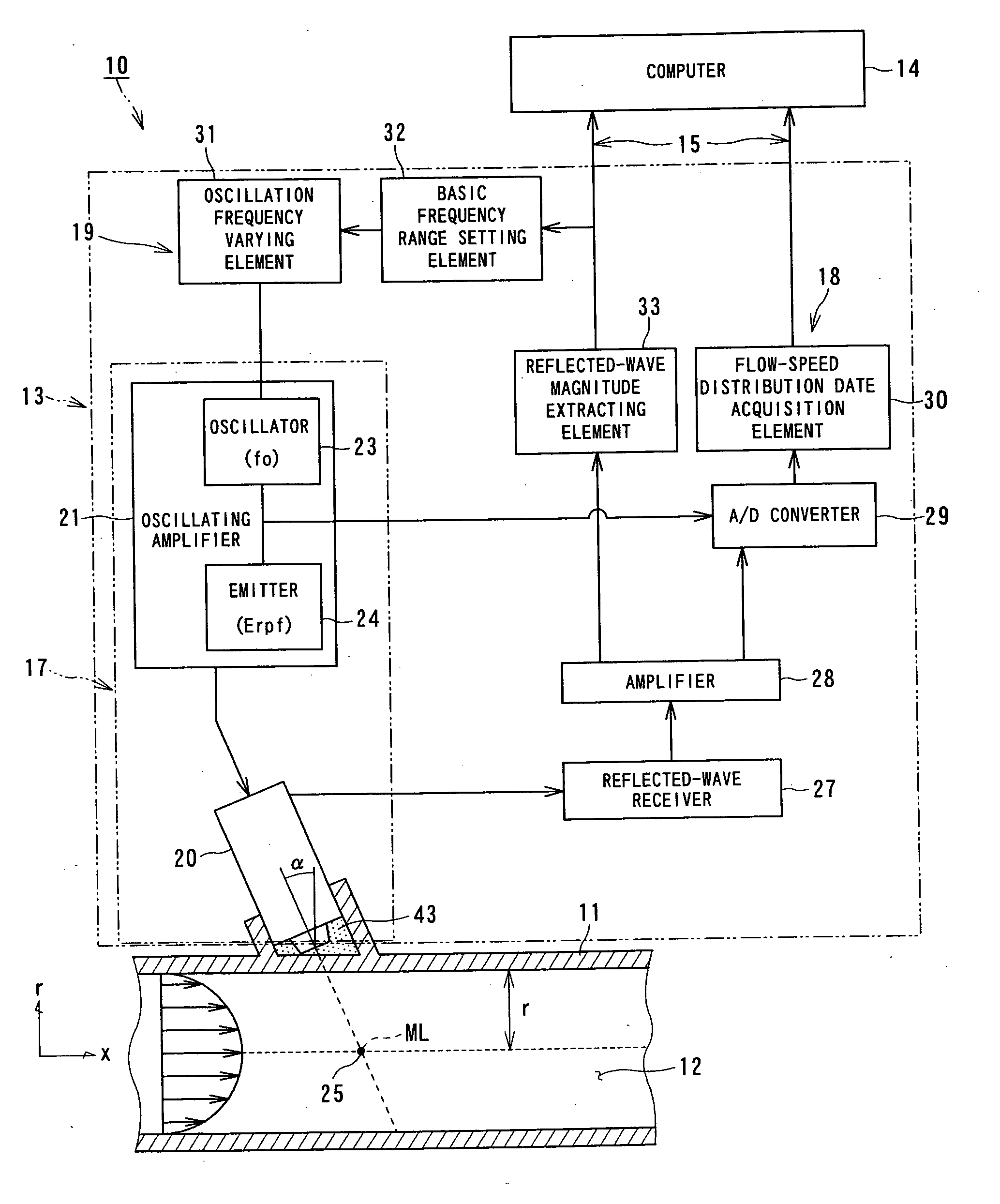
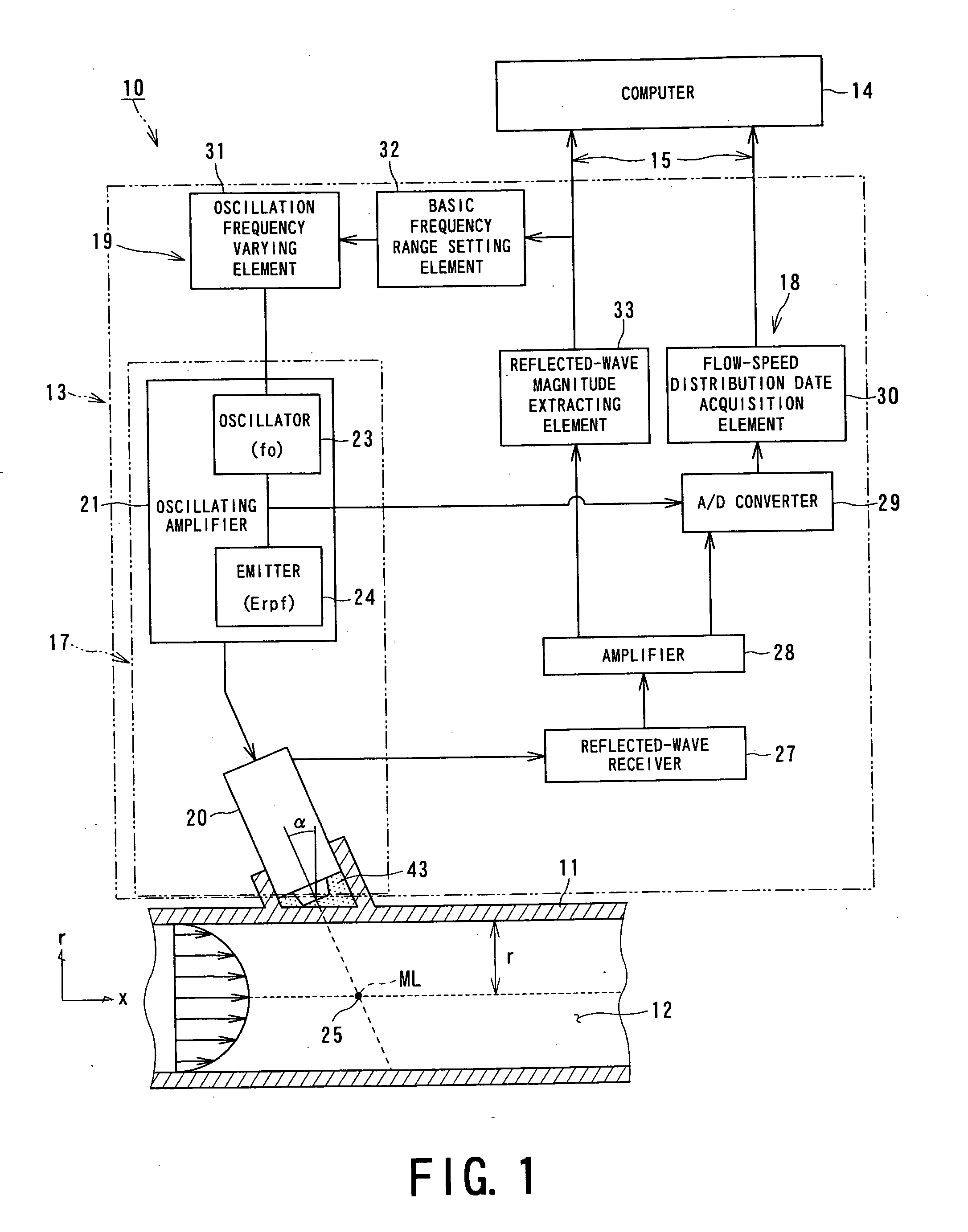
[0147]FIG. 1 is a schematic diagram which shows a schematic configuration of a doppler ultrasonic flowmeter 10 according to a first embodiment of the present invention.
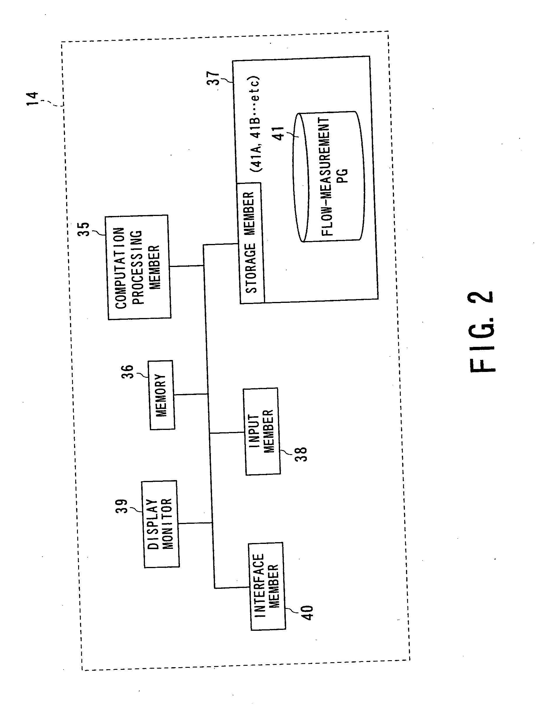
[0148] The doppler ultrasonic flowmeter 10 has a configuration for measuring the flow-speed distribution of a fluid 12 (liquid or gas) which is to be measured, flowing within a fluid tube 11, thereby enabling real-time measurement of the flow over time. The doppler ultrasonic flowmeter 10 comprises an ultrasonic flow-speed distribution data acquisition unit (which will be referred to as “Udflow unit” hereafter) 13 for making measurement of the flow speed of the fluid 12 to be measured, flowing within the fluid tube 11, in a non-contact manner, and a computer 14 for computing the flow-speed distribution of the fluid 12 to be measured based upon the electric signals (data) received from the Udflow unit 13 in order to calculate the flow of the fluid 12 to be measured, and displaying the measurement results thus obtained...
second embodiment
[0167]FIG. 3 is a schematic diagram which shows a schematic configuration of a doppler ultrasonic flowmeter 50 according to a second embodiment of the present invention.
[0168] The doppler ultrasonic flowmeter 50 has a configuration for improving the signal-to-noise (which will be abbreviated to “S / N” hereafter) ratio of the reflected waves, but having no function for selecting and setting the optimum frequency of the ultrasonic pulses cast into the fluid tube 11.
[0169] In order to improve the S / N ratio of the reflected waves, an arrangement may be made wherein the wall thickness of the fluid tube 11 is adjusted such that resonant transmission occurs. However, such a configuration for adjusting the wall thickness of the fluid tube 11 is far from practical. With the present embodiment, the mounting angle of the ultrasonic transducer 20 is adjusted, thereby achieving the same effects as with the aforementioned configuration for adjusting the wall thickness of the fluid tube 11.
[0170...
third embodiment
[0181]FIG. 4 through FIG. 6 are a schematic diagrams which show a schematic configuration of a doppler ultrasonic flowmeter 60 according to a third embodiment of the present invention.
[0182] As shown in FIG. 4, the doppler ultrasonic flowmeter 60 calculates the velocity component V2 of the fluid 12 to be measured, which flows within the flow tube 11, in the ultrasonic incident angle (ultrasonic emission angle) direction, using the doppler frequency. That is to say, the flow-speed distribution is calculated along the measurement line ML based upon the calculated doppler frequency with the line measurement method, thereby calculating the flow of the fluid 12 to be measured.
[0183] That is to say, with the doppler ultrasonic flowmeter 60, the velocity vector V2 along the ultrasonic propagation path (measurement line ML) is calculated based upon the doppler frequency. Then, the calculated velocity vector V2 is divided by (sin α), thereby calculating the velocity vector V1 along the axi...
PUM
 Abstract
Description
Claims
Application Information
 - R&D
- Intellectual Property
- Life Sciences
- Materials
- Tech Scout
- Unparalleled Data Quality
- Higher Quality Content
- 60% Fewer Hallucinations
Browse by: Latest US Patents, China's latest patents, Technical Efficacy Thesaurus, Application Domain, Technology Topic, Popular Technical Reports.
© 2025 PatSnap. All rights reserved.Legal|Privacy policy|Modern Slavery Act Transparency Statement|Sitemap|About US| Contact US: help@patsnap.com


