Cervical brace

a cervical brace and cervical spine technology, applied in the field of cervical spine braces, can solve the problems of obstructing the patient's view, protruding, and less effectively constraining the head movement relative to the torso and spine, and patients cannot wear most off-the-shelf shirts

Inactive Publication Date: 2005-11-03
WASHINGTON UNIV IN SAINT LOUIS
View PDF34 Cites 24 Cited by
  • Summary
  • Abstract
  • Description
  • Claims
  • Application Information

AI Technical Summary

Problems solved by technology

Thus, even though these conventional devices constrain head movement relative to the vest, they less effectively constrain head movement relative to the torso and spine.
Moreover, the frame, and the vertical rods in particular, obstruct the patient's view and protrude in such a way as to inhibit an ordinary lifestyle.
For example, patients cannot wear most off-the-shelf shirts when wearing a conventional cervical brace because the rods interfere with their use.
Although attempts have been made to reduce the motion of vests, the resulting cervical braces obstruct the patient's vision and are not low-profile so they interfere with an ordinary lifestyle.
Moreover, prior cervical braces are time consuming and cumbersome to install due to the large number of screws needed at each adjustment point.
Because cervical braces need frequent adjustment, the large number of screws further increases adjustment time.
Even though conventional braces have a large number of screws, these braces are often particularly difficult to fit to patients with uneven shoulders.
In either case, the loop extends in front of the patient's forehead, thereby further obstructing vision and interfering with an ordinary lifestyle.

Method used


Image

  • Cervical brace
  • Cervical brace
  • Cervical brace

Examples


Embodiment Construction

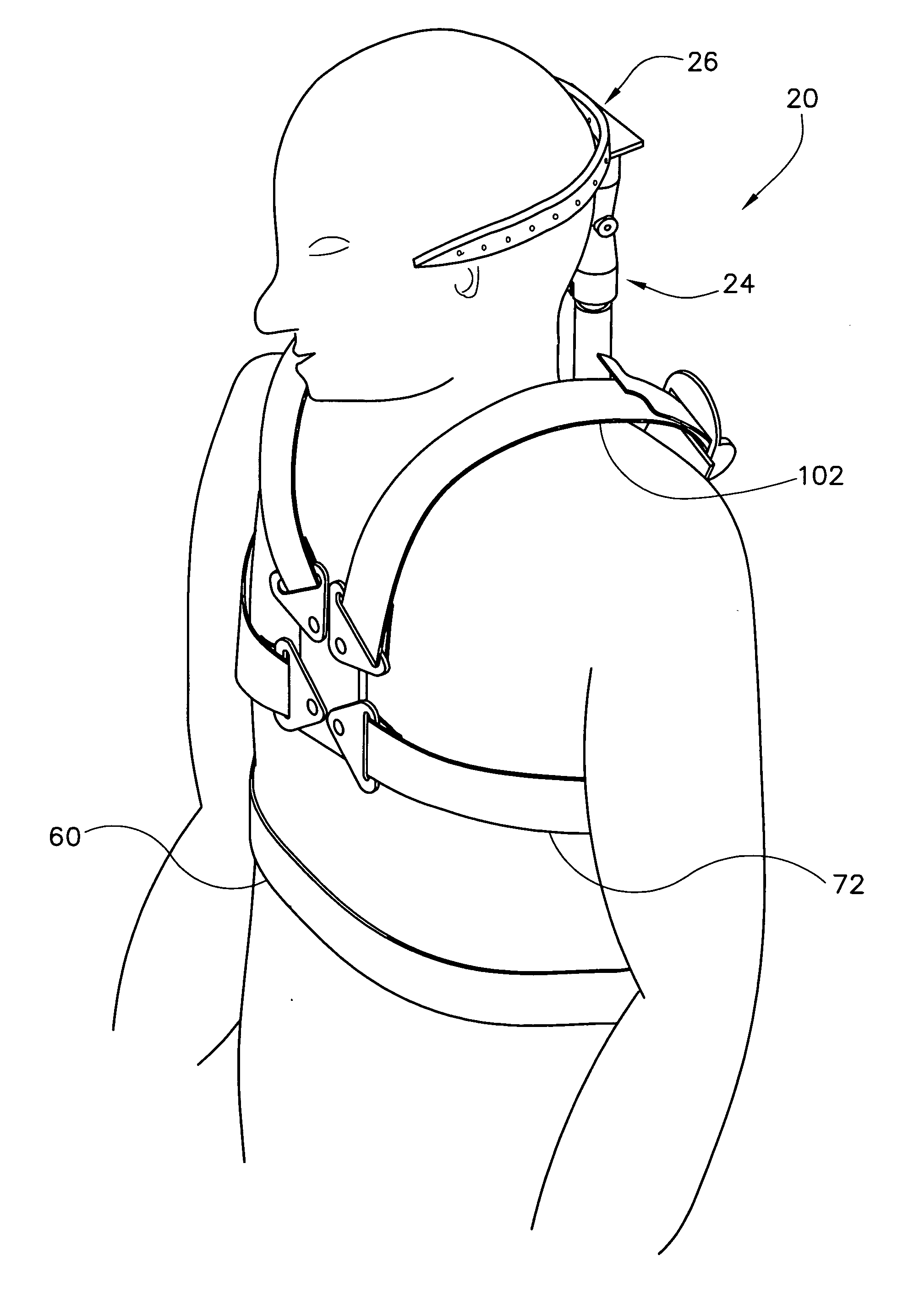
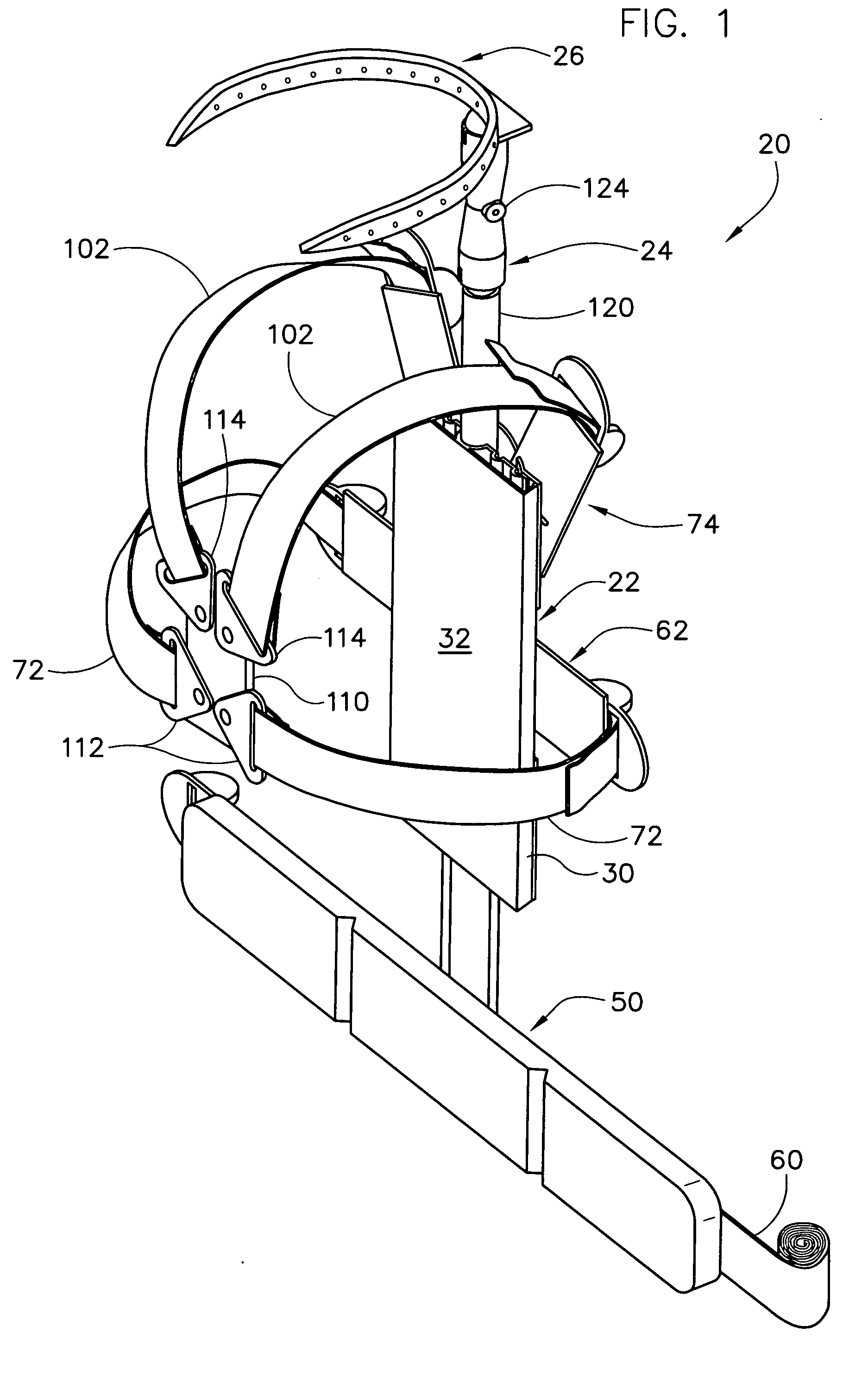
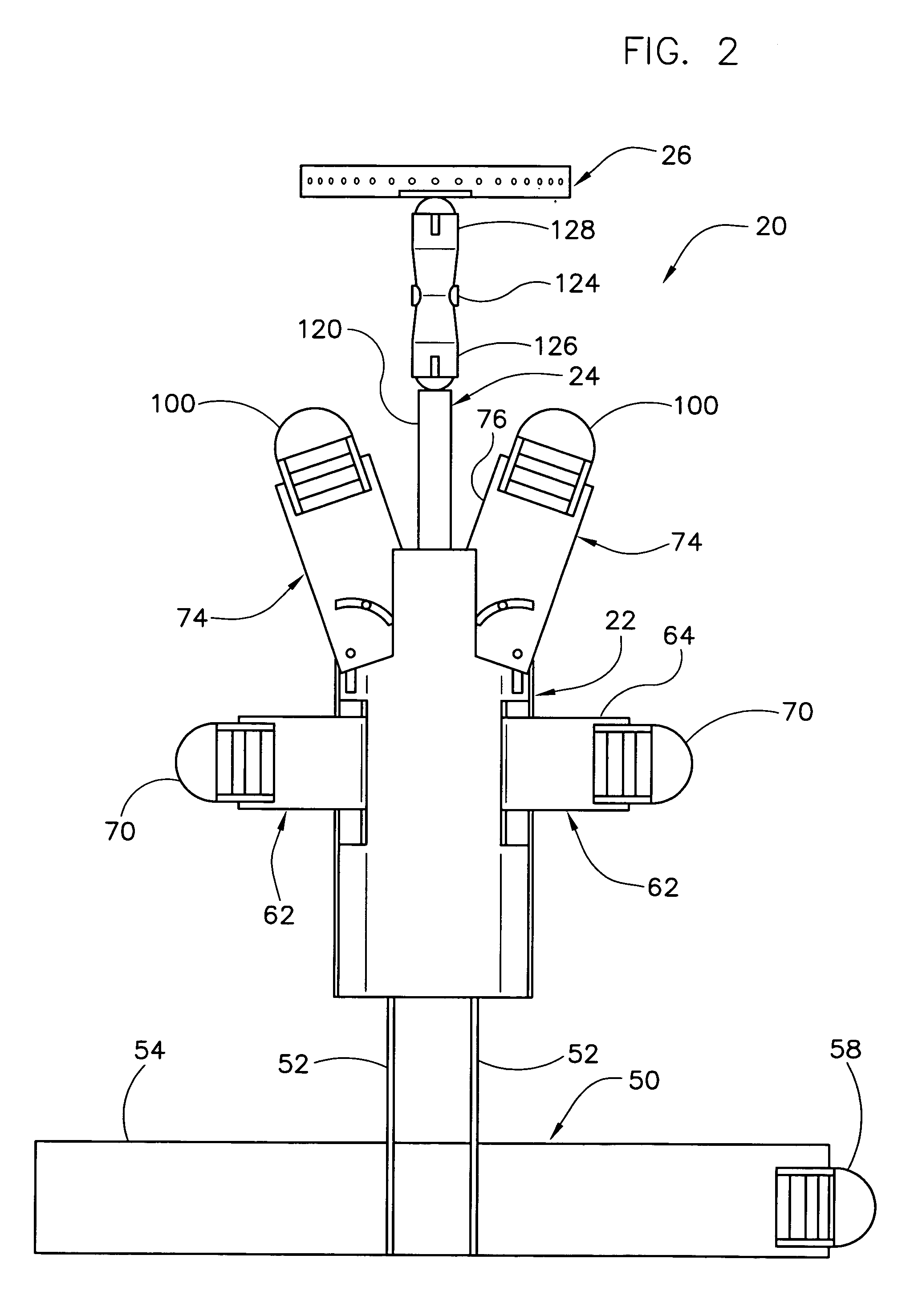
[0018] Referring now to the drawings and in particular to FIGS. 1 and 2, one embodiment of a cervical brace of the present invention is designated in its entirety by the reference numeral 20. The brace 20 generally comprises a mount (generally designated by 22) for attaching the brace to the chest and the abdomen of the patient, a support (generally designated by 24) extending upward from the mount to a position in use adjacent a rearward surface of the head of the patient, and a loop (generally designated by 26) sized and shaped for receiving the head of the patient. As illustrated in FIG. 1, the loop 26 is cantilevered from the support 24.

[0019] As illustrated in FIG. 3, the mount 22 includes a central panel 30 having a generally flat forward face 32 (FIG. 1) and a rearward face 34 opposite the forward face. As shown in FIG. 4, the rearward face 34 has a large central groove 36 extending vertically. Although the groove 36 may have other shapes without departing from the scope of ...


PUM


Abstract

A cervical brace for restraining movement of a head and neck vertebra of a patient relative to at least one of a chest and an abdomen of the patient. The brace includes a mount sized and shaped for attachment to at least one of the chest and the abdomen of the patient and a support extending upward from the mount to a position in use adjacent a rearward surface of the head of the patient. The brace includes a loop sized and shaped for receiving the head of the patient cantilevered from the support. The support includes at least one joint for adjusting at least one of a pitch, a yaw and a roll of the loop relative to the mount.

Description

[0001] This application claims priority from U.S. Provisional Patent Application No. 60 / 564,303 filed Apr. 21, 2004, entitled, “Low Profile, Cantilevered Halo Device”, which is hereby incorporated by reference.BACKGROUND OF THE INVENTION [0002] The present invention relates generally to a cervical brace, and more particularly to a cervical brace having a cantilevered loop. [0003] Cervical braces immobilize a patient's head to facilitate healing of a patient's upper spinal column after a fracture, a dislocation, or a surgery involving the upper spinal column. Generally, cervical braces restrain the head from rolling (such as occurs when a patient tilts her head from side to side), yawing (such as occurs when the patient shakes her head “no”), pitching (such as occurs when the patient nods her head “yes”). Conventional cervical braces immobilize the head by fixing the head to a stiff cast or vest positioned over a patient's torso. Usually, patients wear braces for three to six consecu...

Claims


Application Information

Patent Timeline
Patent Type & Authority Applications(United States)
IPC IPC(8): A61F5/00A61F5/02A61F5/055
CPCA61F5/055A61F5/026
Inventor LEUTHARDT, ERIC C.RIVET, DENNIS J.GENIN, GUY M.ROSENBERG, STUART P.SEGER, LAURA M.TRAN, ELIZABETH L.
Owner WASHINGTON UNIV IN SAINT LOUIS
Why Eureka
Try Eureka