Flow-through bathtub

Inactive Publication Date: 2005-11-10
GALYEAN TINSLEY A JR +1
View PDF11 Cites 48 Cited by
  • Summary
  • Abstract
  • Description
  • Claims
  • Application Information

AI Technical Summary

Benefits of technology

[0014] The invention comprises a continuous flow bathtub having at least two inlets on the head end of the tub, such that water enters the bathtub above a user's shoulders, flowing down over the bather's body and down to the w

Problems solved by technology

Also, in a conventional tub the water is introduced at the foot end of the tub, or at the side, which does not provide the kind of body contact desired.
However, such an arrangement would be contrary to code in many parts of the country, since any water inlet below water level as is shown in this patent would require an anti-siphon device

Method used


Image

  • Flow-through bathtub
  • Flow-through bathtub
  • Flow-through bathtub

Examples


Embodiment Construction

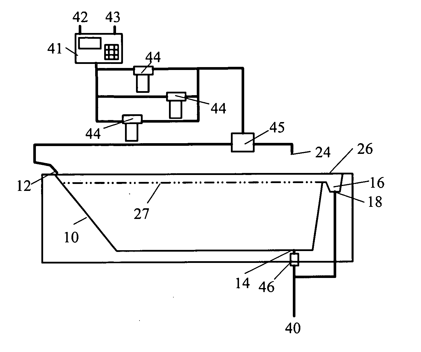
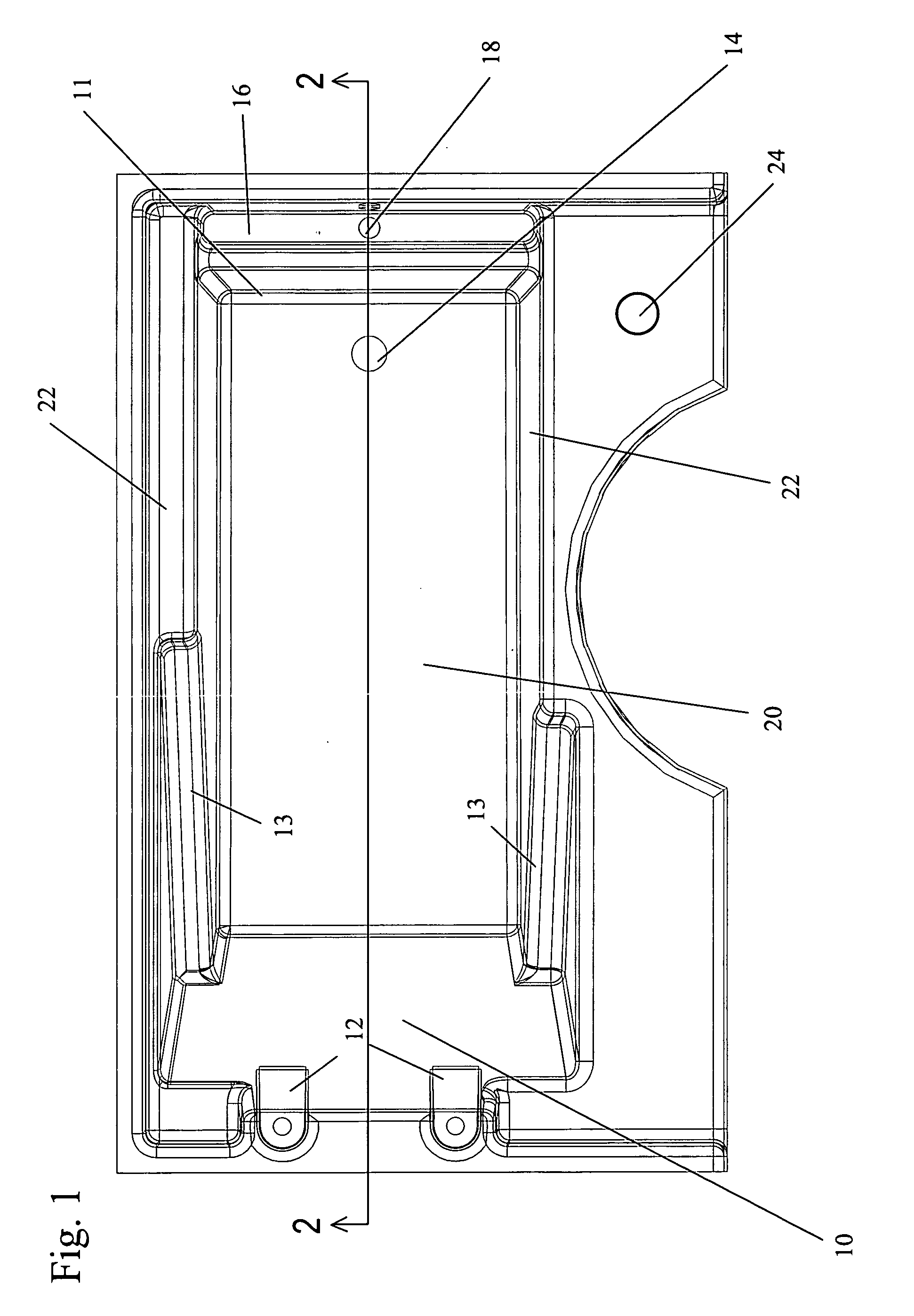
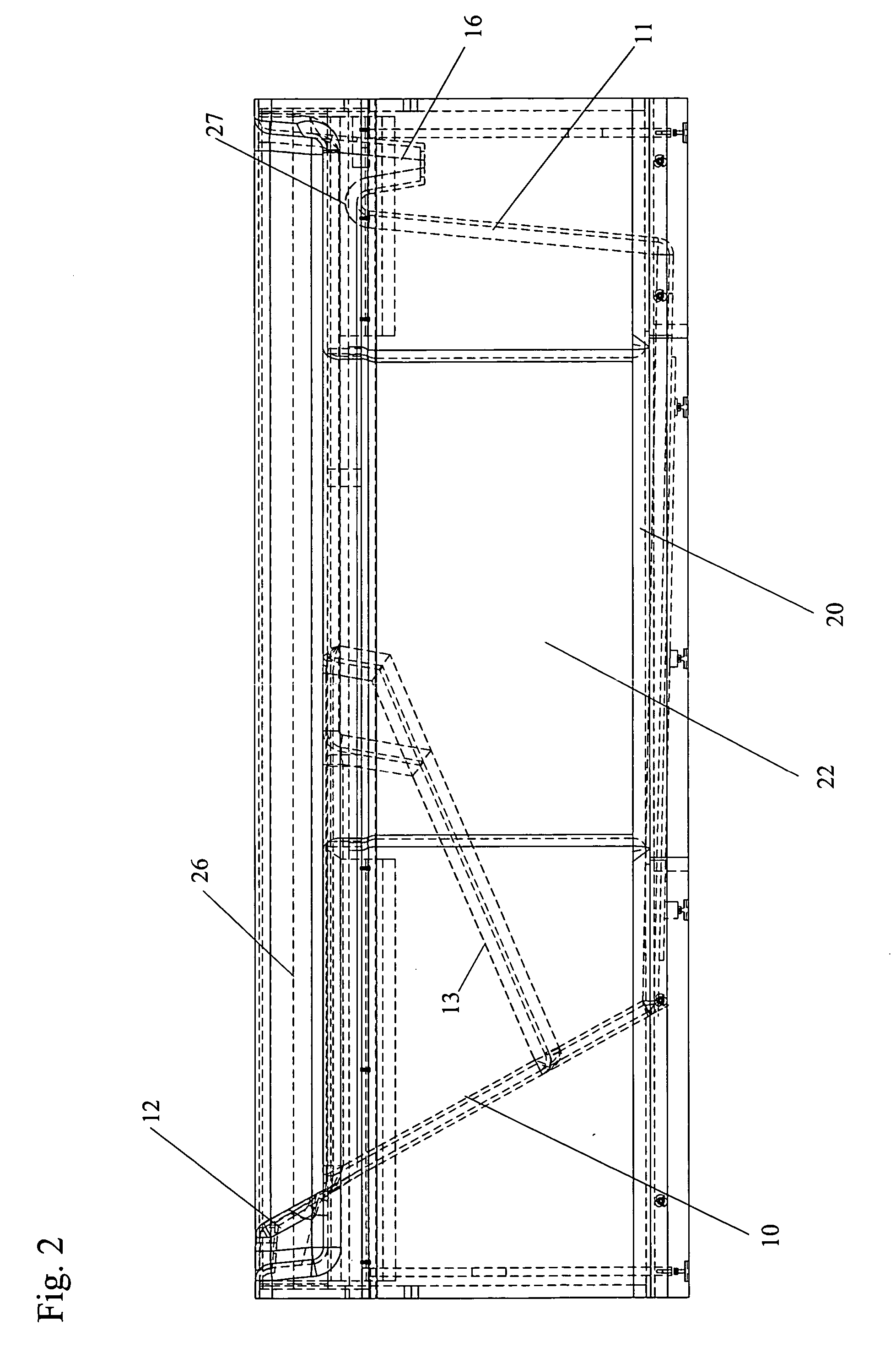
[0019]FIGS. 1-3 shows a therapeutic tub having a head end wall 10 joined to a foot end wall 11 by a bottom 20 and two side walls 22. An overflow trough 16 is present on the foot end wall 11, having a drain (or drains) 18. It is preferred to have two drains 18, but any number of drains sufficient to handle the flow of water could be chosen. Water from drain(s) 18 does not recirculate back into the tub, but is routed into the building drain system. Thus, when the tub is filled to the level of the trough 16, new water introduced at the head end 10 flows into the trough 16 and out the drain 18.

[0020] A faucet 24 for initially filling the tub is located near a side wall 22 of the tub. The faucet 24 may be in line with drain 14 on the bottom of the tub, if desired for aesthetic reasons, but this is not necessary. Bottom drain 14, which car, be closed with a conventional drain valve 46 or a simple stopper in the tub (not shown), allows the entire contents of the tub 10 to be emptied into ...


PUM


Abstract

A continuous flow bathtub having at least two inlets on the head end of the tub, such that water enters the bathtub above a user's shoulders, flowing down over the bather's body and down to the water level in the bathtub, flowing out through an overflow trough at the foot end. This provides a luxurious experience of massage by clean, unused flowing water, without the need for expensive, complicated anti-siphon devices.

Description

BACKGROUND OF THE INVENTION [0001] 1. Field of the Invention [0002] The invention pertains to the field of bathtubs. More particularly, the invention pertains to a bathtub designed to provide a continuous flow of fresh water around a bather. [0003] 2. Description of Related Art [0004] Some early Roman baths, such as those at Bath, England, provided a “flow through” bathing system, in which water drawn from a natural hot spring was piped into a fountain on the north side of a hot pool called the “Great Bath”. A drain on the south side of the pool allowed the water to flow through a drainage system into the River Avon. Since those times, spas have grown up around natural hot springs around the world. [0005] Conventional hydrotherapy tubs or spas typically are filled with water which is then moved around the bather by an impeller, or which is withdrawn from the tub, heated and recirculated through pumps and filters external to the tub and then injected back into the tub through jets. U...

Claims


Application Information

Patent Timeline
IPC IPC(8): A47K3/02A61H33/00A61H33/02
CPCA61H33/0087A61H2205/04A61H33/6068A61H33/601A61H2033/0037
Inventor GALYEAN, TINSLEY A. JR.GALYEAN, EWEN TAYLOR
Owner GALYEAN TINSLEY A JR
Why Eureka
Try Eureka