
Feed control device for plumbing tools

a technology of a control device and a drain, which is applied in the direction of cables, gearing, hoisting equipment, etc., can solve the problems of axial displacement of snakes in opposite directions, structural complexity, and at least somewhat cumbersome arrangement, so as to improve maneuverability and ease of operation

Active Publication Date: 2005-11-10
EMERSON ELECTRIC CO
View PDF18 Cites 14 Cited by
  • Summary
  • Abstract
  • Description
  • Claims
  • Application Information

AI Technical Summary

Benefits of technology

[0006] The control devices which do not require reversal of the direction of rotation of the snake in order to achieve displacement thereof in axially opposite directions are advantageous for a number of reasons. In this respect, for example, operation of the drain cleaning apparatus is made easier for the user by the lafter's not having to manipulate a reversing switch for the drive motor. At the same time, however, the arrangements heretofore provided for axially displacing a snake in opposite directions without changing the direction of rotation of the snake are structurally complex and at least somewhat cumbersome to operate in requiring the user to manipulate at least one and sometimes two components to achieve reversal of the direction of the snake drive. SUMMARY OF THE INVENTION
[0008] It is accordingly an outstanding object of the present invention to provide an improved feed control device for achieving axial displacement of a drain cleaning snake in opposite directions relative to the device.
[0010] A further object is the provision of a feed control device of the foregoing character comprising a minimum number of component parts which are structurally interrelated to promote ease of operation, economy with respect to manufacture, and efficiency with regard to directional displacement of a flexible snake relative to a drain to be cleaned.

Problems solved by technology

At the same time, however, the arrangements heretofore provided for axially displacing a snake in opposite directions without changing the direction of rotation of the snake are structurally complex and at least somewhat cumbersome to operate in requiring the user to manipulate at least one and sometimes two components to achieve reversal of the direction of the snake drive.

Method used


Image

  • Feed control device for plumbing tools
  • Feed control device for plumbing tools
  • Feed control device for plumbing tools

Examples


Embodiment Construction

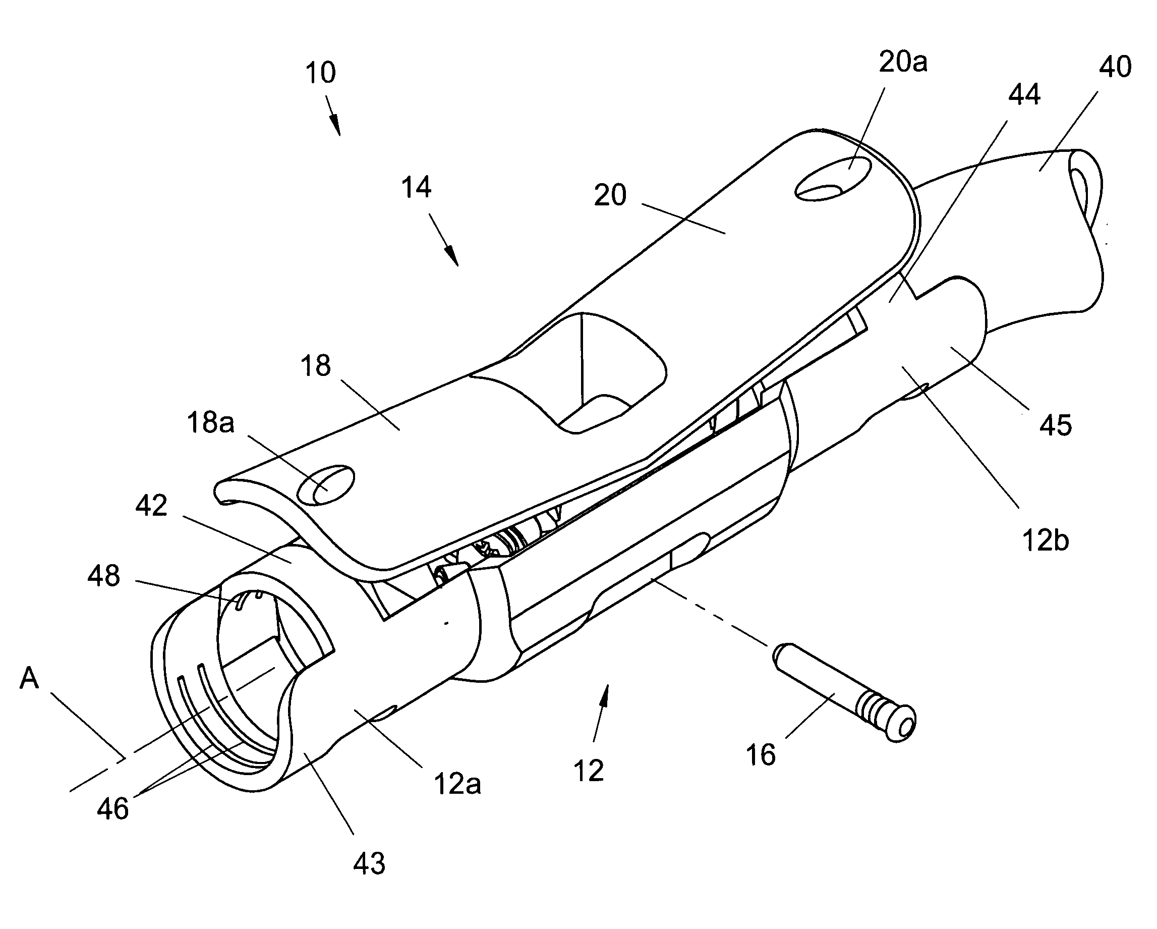
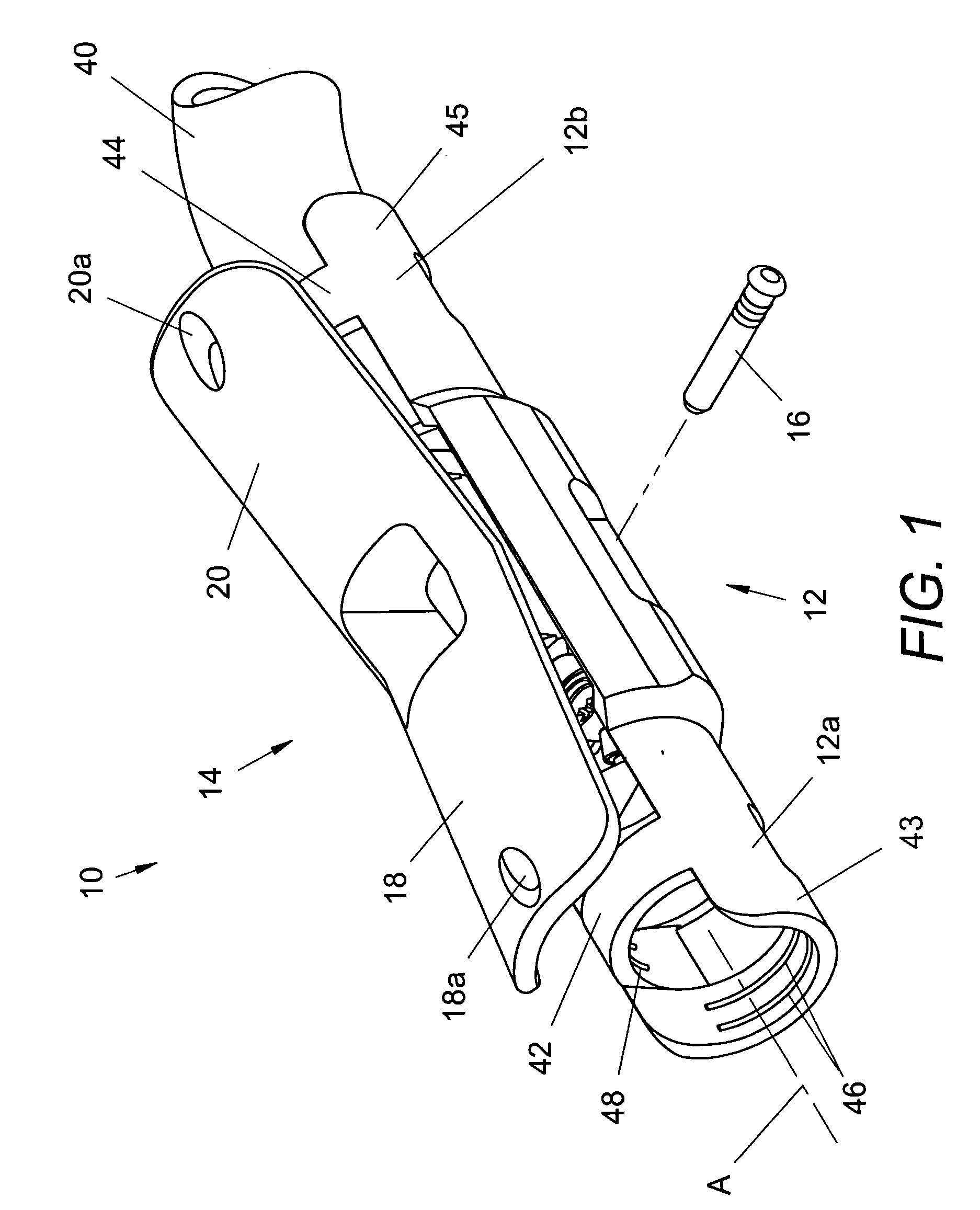
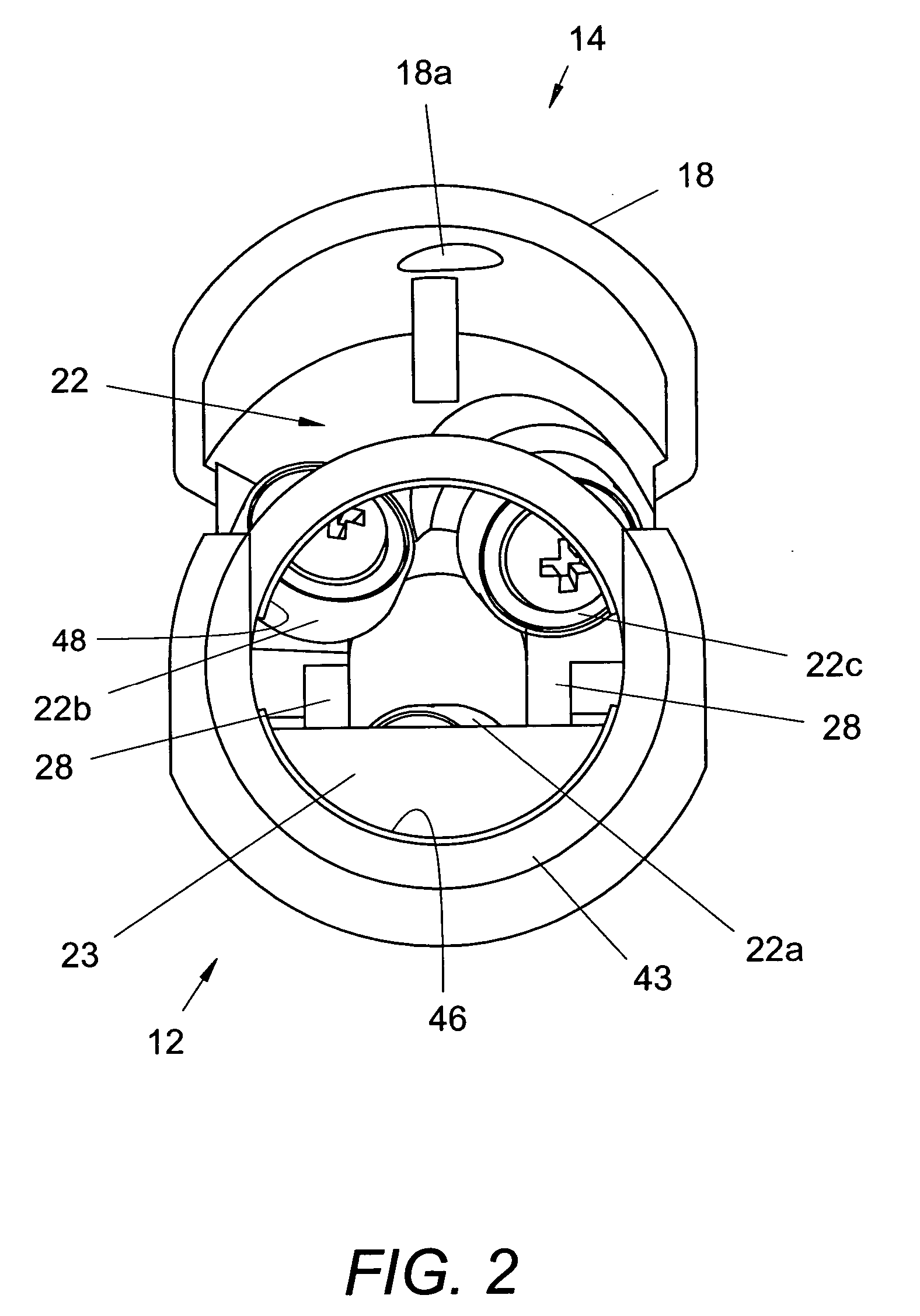
[0030] Referring now in greater detail to the drawings, wherein the showings are for the purpose of illustrating preferred embodiments of the invention only, and not for the purpose of limiting the invention, FIGS. 1-5 illustrate a snake feeding device 10 which, in accordance with the invention, is operable to selectively drive a drain cleaning snake, not shown, in opposite directions relative to axis A of the device. In this embodiment, the device comprises, basically, two component parts, namely a trough-shaped base 12 having axially opposite ends 12a and 12b and an actuator 14 which axially overlies the base and is pivotally interconnected therewith by means of a pin 16 which provides a pivot axis B transverse to axis A and generally centrally between the opposite ends of the base. The base and actuator components can be of metal or a suitable plastic such as, for example, a fiber filled polypropylene. Actuator 14 includes legs 18 and 20 extending in axially opposite directions r...


PUM


Abstract

A snake feeding device comprises a base having opposite ends, an actuator pivotally mounted on the base, and first and second sets of drive rolls spaced apart in the direction between ends of the base. Each set includes a roll on the base and two rolls on the actuator for engaging a snake therebetween and displacing the snake relative to the base in the direction between the ends thereof in response to rotation of the snake. The actuator selectively displaces the rolls of each set relative to one another.

Description

BACKGROUND OF THE INVENTION [0001] This application is a continuation-in-part of application Ser. No. 10 / 792,983 filed Mar. 4, 2004.[0002] This invention relates to the art of drain cleaning apparatus and, more particularly, to an improved feed control arrangement by which a flexible snake of such apparatus can be axially advanced and retracted relative thereto during a drain cleaning operation. [0003] It is of course well known to provide manually operable feed control devices for advancing and retracting a drain cleaning snake relative to a drain being cleaned. In some such devices, a plurality of rolls are supported in a housing, or the like, through which the snake extends, and the rolls are spaced apart about the periphery of the snake. The rolls have neutral and engaged positions relative to the snake and in which the snake, when rotated, respectively rotates in place and is axially displaced relative to the housing. In some designs, the rolls are skewed relative to the axis o...

Claims


Application Information

Patent Timeline
IPC IPC(8): B08B9/04
CPCB08B9/045E03F9/005Y10T74/1973Y10T74/19744F16L55/24
Inventor RUTKOWSKI, MICHAEL J.DUNKIN, JON R.
Owner EMERSON ELECTRIC CO
Learn More