Carabiner with improved gate structure

a technology of gate structure and carabiner, which is applied in the field of carabiners, can solve the problems of many inconveniences for manufacturers or users, and the carabiner can afford the smallest strength among all carabiners, so as to facilitate assembly, improve the gate structure, and facilitate control

Inactive Publication Date: 2005-11-10
HSU SAMUEL WEN CHIH
View PDF4 Cites 43 Cited by
  • Summary
  • Abstract
  • Description
  • Claims
  • Application Information

AI Technical Summary

Benefits of technology

[0013] Accordingly, the purpose of the present invention is to provide a carabiner with improved gate structure. The carabiner with improved gate structure according to the present invention includes a metal hook and a locking mechanism. The metal hook is generally designed as a C-shaped or D-shaped body, in which a body portion is disconnected as a gate loaded with a locking mechanism.
[0014] Provided locking mechanism is composed of a safety latch, a tip, an inwardly and outwardly compressed spring, and a cylindrical latching arrangement. Wherein, the safety latch is a shaft with a recessed notch having an inwardly compressed spring and a tip, which is pivotally attached to the fixed end of the metal hook and against the fixed end at one time in order to control the largest sway movement of the locking mechanism. Another end of the safety latch is a clip-in end, in which a axial punch cooperates with a bar for the hook-up of the metal hook end. Whether the safety latch 31 and metal hook 21 is hooked up or not can be controlled by the cylindrical latching arrangement 4. When the cylindrical latching arrangement is sleeved to the outer part of the safety latch, it is push by a compressed spring loaded on the outer part of the safety latch. A tilting slotted guide on interior wall of the cylindrical latching arrangement is used to fit with the orient ball bearing predetermined on the safety latch wall. Therefore, users can easily clip the outer part of the cylindrical latching arrangement with fingers, and then rotate and displace it pivotally, which makes the opening of said gate easier and more convenient. When locking said gate, after the locking mechanism is returned to its original position, the cylindrical latching arrangement can be pushed backward to a fixed position with little force through compressed springs, which accelerates the control and use of said locking mechanism.
[0015] Another objective of the present invention is to provide a carabiner with improved gate structure, wherein the cylindrical latching arrangement and the safety latch is operated by allowing the orient ball bearing to slide and fit within the slotted guide, which permits easier control and facilitates assembling.
[0016] Another objective of the present invention is to provide a carabiner with improved gate structure, in which the life of the cylindrical latching arrangement and safety latch can be increased by allowing a orient ball bearing to be slid to fit within a slotted guide.
[0017] Still another objective of the present invention is to provide a carabiner with improved gate structure, wherein varying slotted guides defined in the interior wall of the cylindrical latching arrangement can be designed for multiple-mode control suitable for various place use.

Problems solved by technology

Nevertheless, such carabiners can afford the littlest strength among all carabiners.
Unfortunately, conventional carabiners cause many inconvenience to both manufacturers and users.
However, such a structure may bring much inconvenience to manufacturers or users.
The problems include the internal space of the cylindrical locking element is too narrow to load a screw-type spring, and loading a screw-type spring defined on a vertical elongated slot is not easy.
Aside from these, since the cylindrical locking element is locked and released only by the elasticity of the screw-type spring, the screw-type spring may lose its elasticity, which further affects users' safety.

Method used


Image

  • Carabiner with improved gate structure
  • Carabiner with improved gate structure
  • Carabiner with improved gate structure

Examples


Embodiment Construction

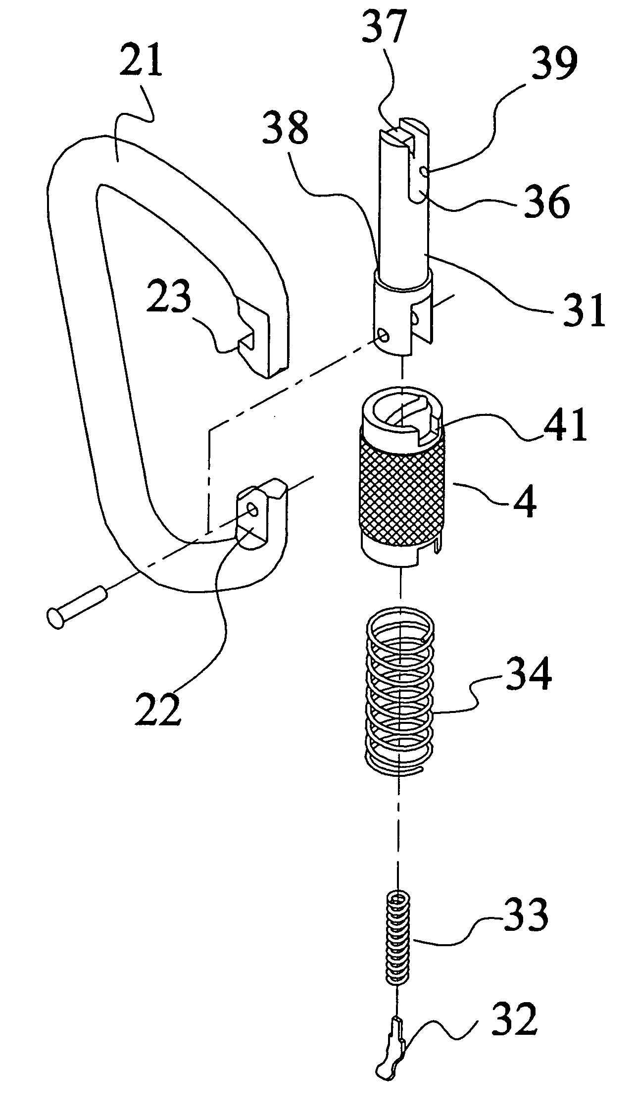
[0033] In the carabiner with improved gate structure of the present invention, as shown in FIG. 2, the carabiner with improved gate structure 2 mainly composes a metal hook 21 and a locking mechanism 3. The metal hook 21 is approximately shaped as, a C or D-type body, wherein a body portion is disconnected as the use of a gate and a locking mechanism 3 is provided on the gate.

[0034] Referring to FIGS. 3 and 4, the locking mechanism 3 is composed of a safety latch 31, a tip 32, an inwardly and outwardly compressed spring 33, 34, and a cylindrical latching arrangement 4, in which said safety latch 31 is a shaft with each end is double-edged. An axial recessed notch 35 is defined on part of the shaft to load a inwardly compressed spring 33 and tip 32. When the tip 32 with an outer arc end is pushed outward by the inwardly compressed spring 33, its outer arc end is against the interior fringe of the fixed end 22 on the metal hook. After the fixed end of a safety latch 31 is pivotally c...


PUM


Abstract

A carabiner with improved gate structure comprises: a metal hook and a locking mechanism; wherein the locking mechanism is composed of a safety latch, a tip, an inwardly and outwardly compressed spring, and a cylindrical latching arrangement; one end of the safety latch is pivotally cooperated with the fixed end of a metal hook, with a tip against the fixed end, and another end of the safety latch includes a clip-in opening for clip-in of the metal hook end; a cylindrical latching arrangement is sleeved to the external part of the safety latch, the invention is characterized in: providing an easier way to control the cylindrical latching arrangement and safety latch with a means that allows a orient ball bearing to slide to fit within a slotted guide.

Description

BACKGROUND OF THE INVENTION [0001] 1. Field of the Invention [0002] The present invention relates to a carabiner, and more particular to a carabiner with improved gate structure, in which the control and use of a cylindrical latching arrangement can be easier and safer by allowing a orient ball bearing to slide to fit within a slotted guide, providing easier access to multiple-stage control. [0003] 2. Description of the Prior Art [0004] Accordingly, the generating of the carabiner is to ensure the safety of operating personnel. Various carabiners with different shape and size are generated in accordance with different using environment and conditions to meet the needs of different usage. There are various types of carabiners, which can be distinguished into three categories according to their shape: Oval Carabiners: the Earliest Shape of Carabiners. [0005] The internal part of such carabiners has larger space to hang a number of devices without congestion. Also, the design of smoot...

Claims


Application Information

Patent Timeline
Patent Type & Authority Applications(United States)
IPC IPC(8): F16B45/02
CPCY10T24/45277F16B45/02F16B45/026F16B45/029F16B45/023
Inventor HSU, SAMUEL WEN-CHIH
Owner HSU SAMUEL WEN CHIH
Why Eureka
Try Eureka