Ergonomic handle for a utility knife

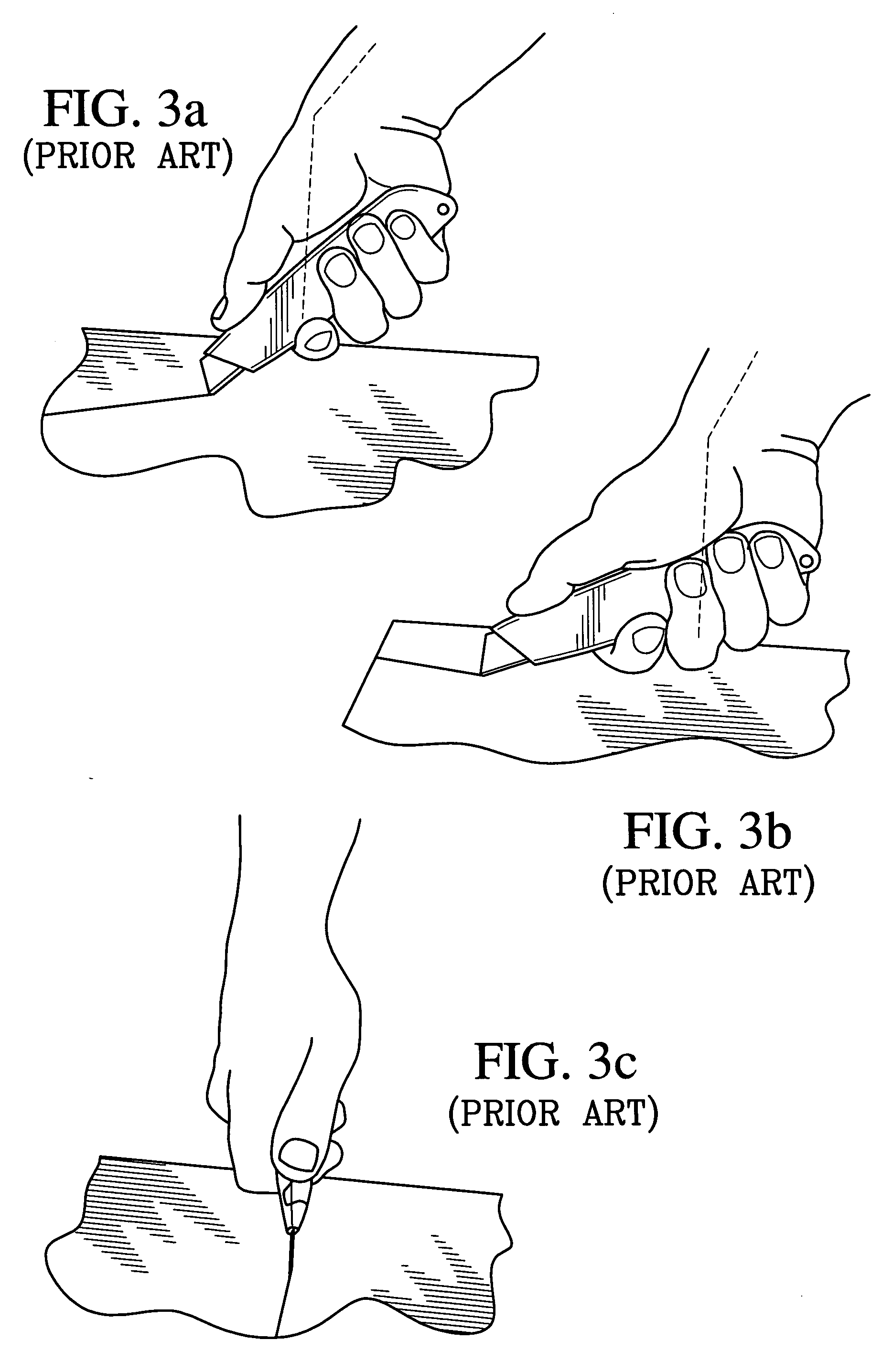
a handle and utility knife technology, applied in the field of ergonomic handles, can solve the problems of users that must cut regularly, the blade cannot touch the cutting plane, and the muscles used for ulnar deviation are disproportionately stressed, so as to achieve the effect of avoiding inflammation and pain and requiring more for

Inactive Publication Date: 2005-11-10
YEAGER ARTHUR F
View PDF17 Cites 7 Cited by
  • Summary
  • Abstract
  • Description
  • Claims
  • Application Information

AI Technical Summary

Benefits of technology

[0007] The utility knife and handle of the present invention overcome the limitations of the devices as briefly described above, by providing a design that allows a user to maintain a neutral wrist position while using the stronger flexor muscles to exert force. The larger muscles of the forearm can exert more force for longer periods than the muscles used for wrist deviation. The avoidance of ulnar wrist deviation avoids inflammation and pain caused by repeated compression of the synovial sheaths.

Problems solved by technology

Unfortunately, the design of a utility knife does not allow the blade to contact a cutting plane without deviating the wrist out of a neutral position.
This potentially harmful position is compounded by an uneven mechanical leverage causing disproportionate stress on the muscles used for ulnar deviation.
At higher risk are users that must cut regularly throughout the work day.
These users must repeatedly deviate their wrist ulnarly which can lead to a painful diagnosis called radial tenosynovitis or De Quervain's Syndrome.
If untreated, this condition can eventually require surgery with significant rehabilitation time.
Regardless of how much the angle is changed, it is physically impossible to use prior art knives without deviating the wrist and exerting heavy forces to one muscle group.

Method used


Image

  • Ergonomic handle for a utility knife
  • Ergonomic handle for a utility knife
  • Ergonomic handle for a utility knife

Examples


Embodiment Construction

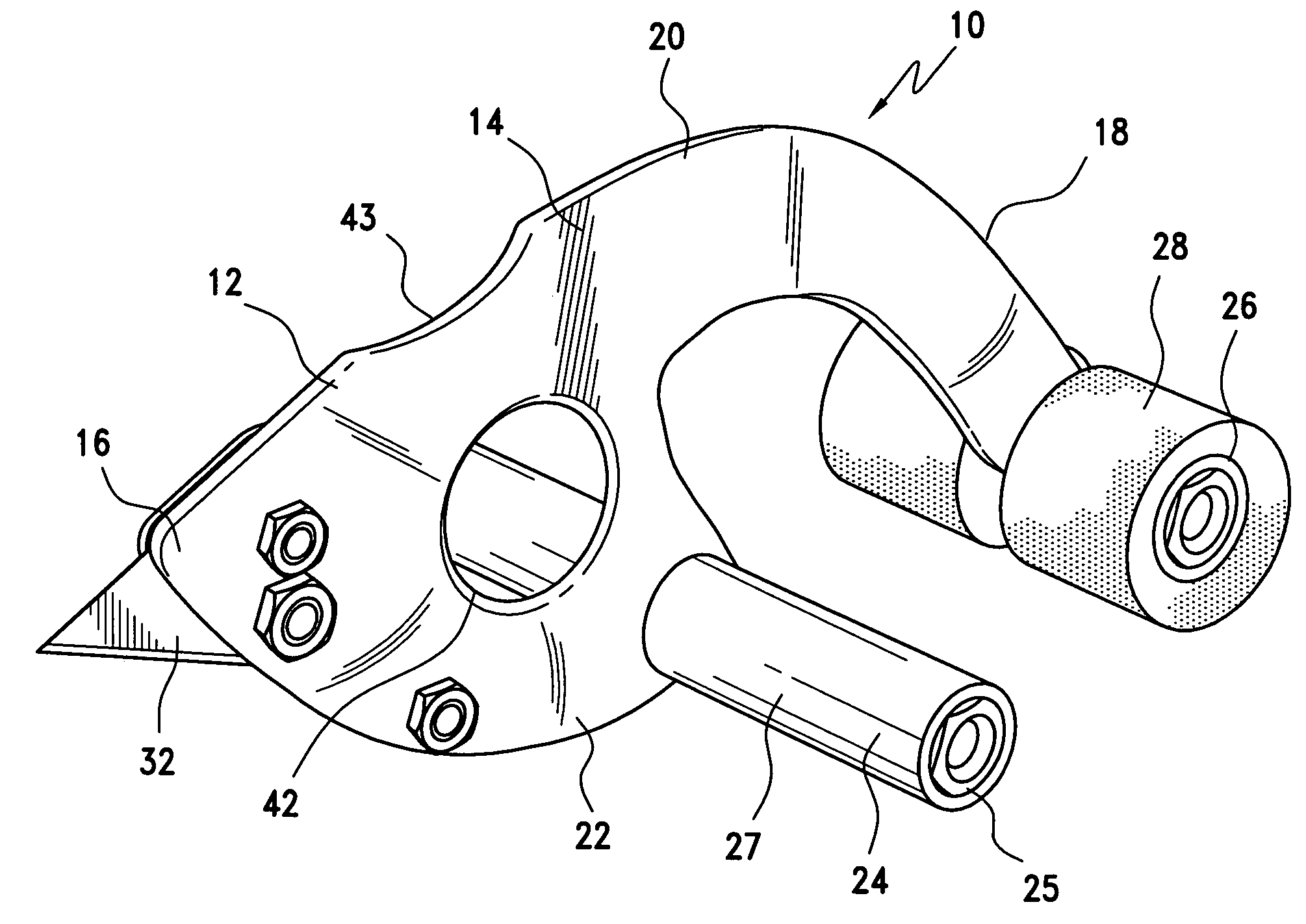
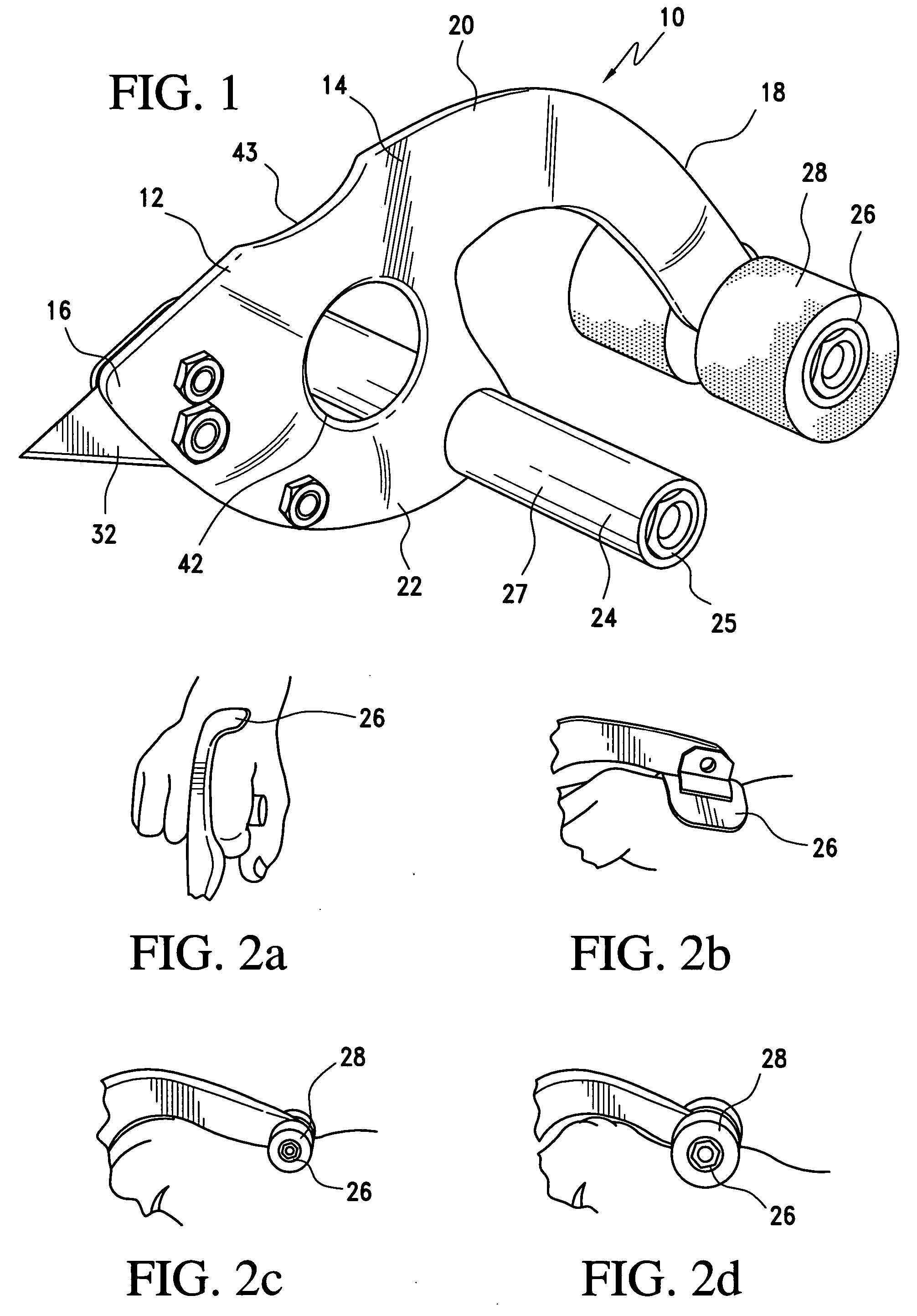
[0027] Referring to FIG. 1, shown is a utility knife 10.comprising a handle 12 of the present invention. The handle 12 includes a body 14. The handle body 14 comprises a first end 16, a second end 18, a top portion 20 and a bottom portion 22. The body 14 may be comprised of a variety of materials, including but not limited to non-flexible plastic including high strength molded plastic; wood; and metal including galvanized metal or a lightweight alloy such as aluminum. Preferably, the body is comprised of molded plastic. All or portions of the handle body 14 may be hollow in order to decrease the weight of the handle 12 and utility knife 10.

[0028] The handle 12 further includes a grip 24 connected to the body 14 and preferably located substantially perpendicular to the body. The grip 24 forms what is commonly known as a T-grip with the body 14. The grip 24 may be any shape which enables a user to grasp and utilize the handle 12 while maintaining the user's wrist in a neutral positio...


PUM


Abstract

The present invention is directed to an ergonomic handle for a tool such as a utility knife. The handle includes a body having a first end and a second end. The body includes a lever arm attached to the second end of the body and a grip connected to and located perpendicular to the body. The lever arm rests against the back of a user's hand thereby stabilizing the handle during use.

Description

I. BACKGROUND OF THE INVENTION [0001] 1. Field of the Invention [0002] The present invention relates to utility knives. More particularly, the present invention relates to an ergonomically shaped handle for utility knives and other hand-held tools. [0003] 2. Discussion of the Related Art [0004] Utility knives are used for a variety of tasks each requiring different levels of force to be transmitted through the cutting blade. Almost all knives used with medium to heavy force are designed to be held with a gross grasp that forms a composite fist. Such a grip allows one to use larger muscle groups in the shoulder and arm rather than the weaker wrist. Unfortunately, the design of a utility knife does not allow the blade to contact a cutting plane without deviating the wrist out of a neutral position. This potentially harmful position is compounded by an uneven mechanical leverage causing disproportionate stress on the muscles used for ulnar deviation. [0005] For most occasional users th...

Claims


Application Information

Patent Timeline
Patent Type & Authority Applications(United States)
IPC IPC(8): B26B1/00B26B3/00B26B5/00B26B29/02
CPCB26B3/00B26B29/025B26B29/02B26B5/00
Inventor YEAGER, ARTHUR F.
Owner YEAGER ARTHUR F
Why Eureka
Try Eureka