
Arthroscopic devices and methods

a technology of arthroscopic devices and tissue, applied in the field of arthroscopic tissue cutting and removal devices, can solve the problems of joint failure, wear and tear, and loss of micro-particles from fracture and particle release, and achieve the effect of preventing foreign particle induced inflammation

Active Publication Date: 2017-03-07
RELIGN CORP
View PDF118 Cites 43 Cited by
  • Summary
  • Abstract
  • Description
  • Claims
  • Application Information

AI Technical Summary

Benefits of technology

The present invention provides a medical device with a cutting member that can be used to cut bone tissue without leaving any foreign particles in the site. The cutting member is made of a wear-resistant ceramic material and is engaged against bone and rotated using a motor. This device helps prevent inflammation and promotes healing at the bone treatment site.

Problems solved by technology

When metal shavers and burrs “wear” during a procedure, which occurs very rapidly when cutting bone, the wear can be accompanied by loss of micro-particles from fracture and particle release which occurs along with dulling due to metal deformation.
In such surgical applications, even very small amounts of such foreign particles that are not recovered from a treatment site can lead to detrimental effects on the patient health, with inflammation being typical.
In some cases, the foreign particles can result in joint failure due to osteolysis, a term used to define inflammation due to presence of such foreign particles.
In addition to causing inflammation, the presence of metal particles in a joint or other treatment site can cause serious problems for future MRIs.
Typically, the MRI images will be blurred by agitation of the metal particles caused by the magnetic field used in the imaging, making assessments of the treatment difficult.
Another problem with the currently available metal shavers / burrs relates to manufacturing limitations in combination with the rapid dulling of metal cutting edges.
The flute shape and geometry can be limited since it is dictated by the machining process, and burr size and shape limitations may direct usage toward more coarse bone removal applications.
Further, when operated in a rotational or oscillatory mode, the cutting edges adapted for coarse bone removal may have a kickback effect as the flutes first make contact with bone, which is aggravated by rapid dulling of the machined cutting edges.

Method used


Image

  • Arthroscopic devices and methods
  • Arthroscopic devices and methods
  • Arthroscopic devices and methods

Examples


Embodiment Construction

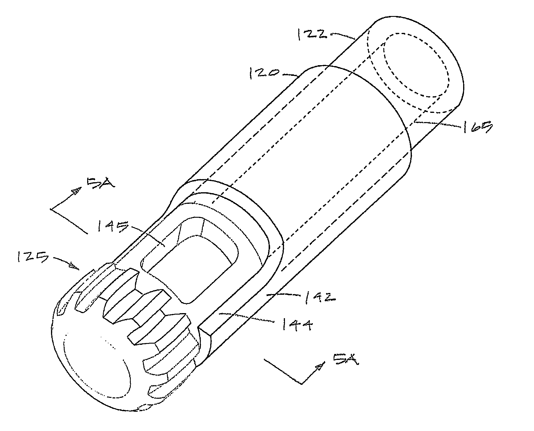
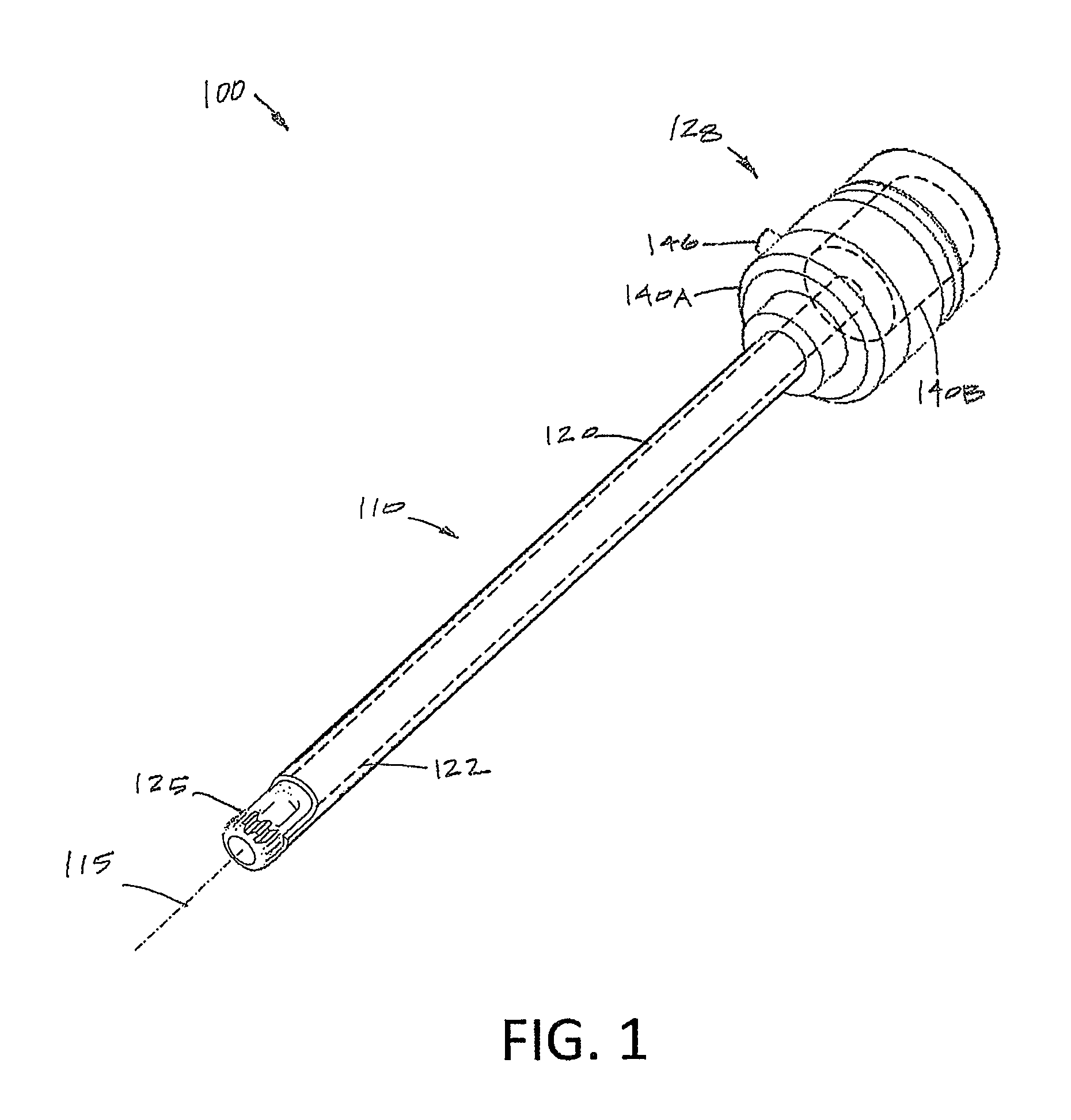
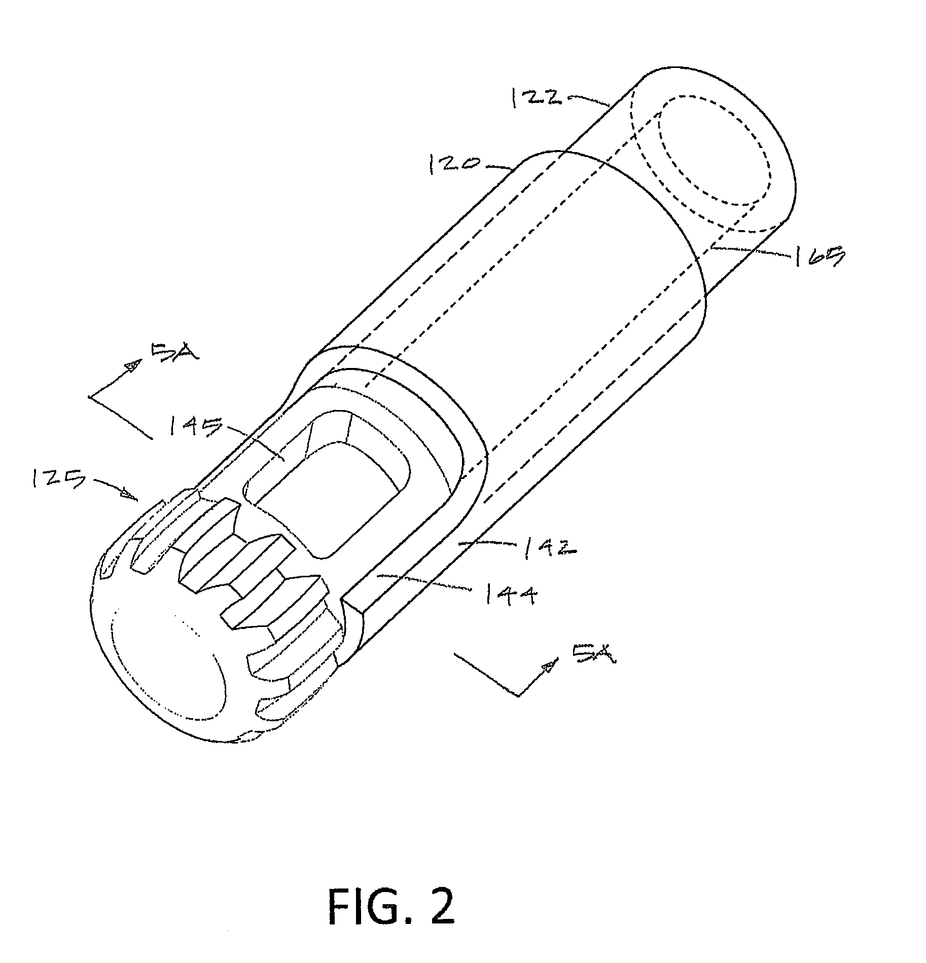
[0036]The present invention relates to bone cutting and removal devices and related methods of use. Several variations of the invention will now be described to provide an overall understanding of the principles of the form, function and methods of use of the devices disclosed herein. In general, the present disclosure provides for an arthroscopic cutter or burr assembly for cutting or abrading bone that is disposable and is configured for detachable coupling to a non-disposable handle and motor drive component. This description of the general principles of this invention is not meant to limit the inventive concepts in the appended claims.

[0037]In general, the present invention provides a high-speed rotating ceramic cutter or burr that is configured for use in many arthroscopic surgical applications, including but not limited to treating bone in shoulders, knees, hips, wrists, ankles and the spine. More in particular, the device includes a cutting member that is fabricated entirely ...


PUM


Abstract

A medical device includes an elongated sleeve having a longitudinal axis, a proximal end and a distal end. A cutting member extends distally from the distal end of the elongated sleeve, and has sharp cutting edges. The cutting head is formed from a wear-resistant ceramic material, and a motor coupled to the proximal end of elongated sleeve rotate the cutting member. The cutter is engaged against bone and rotated to cut bone tissue without leaving any foreign particles in the site.

Description

CROSS-REFERENCE TO RELATED APPLICATIONS[0001]This application claims the benefit of provisional application 62 / 250,315, filed on Nov. 3, 2015, and of provisional application 62 / 245,796, filed on Oct. 23, 2015, the full disclosures of which are incorporated herein by reference.BACKGROUND OF THE INVENTION[0002]1. Field of the Invention[0003]This invention relates to arthroscopic tissue cutting and removal devices by which anatomical tissues may be cut and removed from a joint or other site. More specifically, this invention relates to instruments configured for cutting and removing bone or other hard tissue and having a ceramic cutting member.[0004]2. Description of the Background Art[0005]In several surgical procedures including subacromial decompression, anterior cruciate ligament reconstruction involving notchplasty, and arthroscopic resection of the acromioclavicular joint, there is a need for cutting and removal of bone and soft tissue. Currently, surgeons use arthroscopic shaver...

Claims


Application Information

Patent Timeline
IPC IPC(8): A61B17/16A61B17/00
CPCA61B17/1615A61B17/1628A61B17/1631A61B2017/00473A61B2017/0023A61B2217/005A61B2017/0088A61B17/1626A61B17/1633A61B2017/22079A61B2017/320028A61B2217/007A61B17/32002A61B17/1637A61B18/148A61B2017/00039A61B2017/00836A61B2018/00577A61B2018/00601A61B2018/00702A61B2018/142A61B2218/007
Inventor GERMAIN, AARONKLEIN, KYLEWALKER, MICHAEL D.
Owner RELIGN CORP
Learn More