Pivoting jig head for a fishing lure

a technology of jig head and lure, which is applied in the field of jig head fixed in an immovable fashion to the hook, can solve the problems of severely restricting the swimming or undulating motion available to the attractor portion of the combination, and achieves the effect of easy replacemen

Inactive Publication Date: 2005-11-10
MITCHELL ALLAN DAVID
View PDF33 Cites 18 Cited by
  • Summary
  • Abstract
  • Description
  • Claims
  • Application Information

AI Technical Summary

Benefits of technology

[0034] The present invention is a jig head, to which a fishing lure may be attached, that can pivot on a fish hook or clip to attract fish as it is pulled through the water on a fishing line. There is a channel through the jig head, through which the fish hook or clip is inserted, so that the jig head (and the attached lure) can pivot on the hook or clip. As the fish hook is not permanently attached to the jig head, it will be easy to replace a worn or damaged hook, while reusing the jig head with a new hook. There may be a second channel through the jig head, through which water can flow, to further attract fish by the sound of the water flowing through the jig head and lure, and optionally to help disperse an attractive scent from the lure into the water.

Problems solved by technology

A problem with the prior art is that the jig head is fixed in an immovable fashion to the hook.
This severely limits the swimming or undulating motion available to the attractor portion of the combination.

Method used


Image

  • Pivoting jig head for a fishing lure
  • Pivoting jig head for a fishing lure
  • Pivoting jig head for a fishing lure

Examples


Embodiment Construction

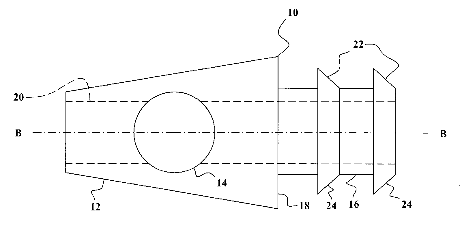
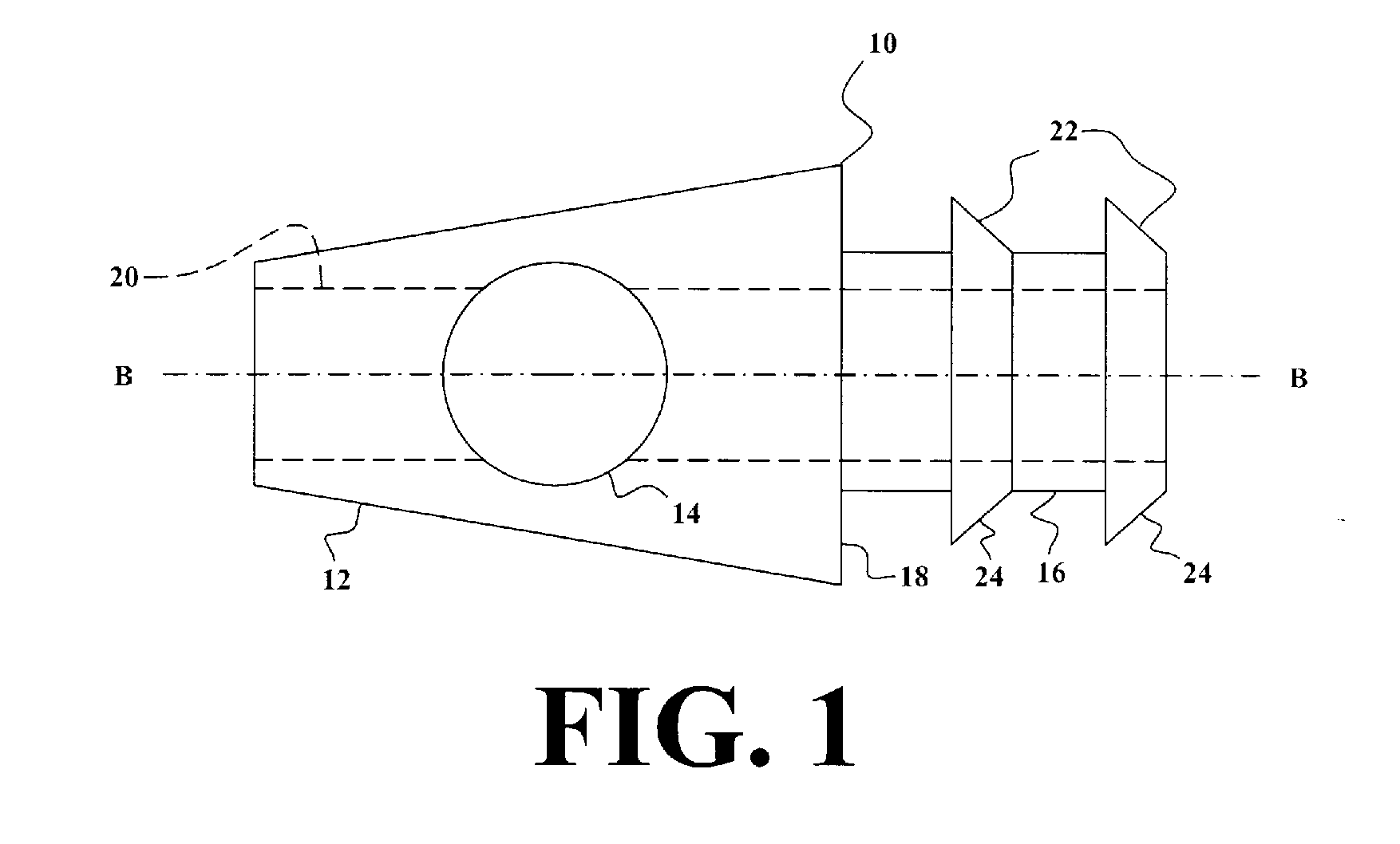
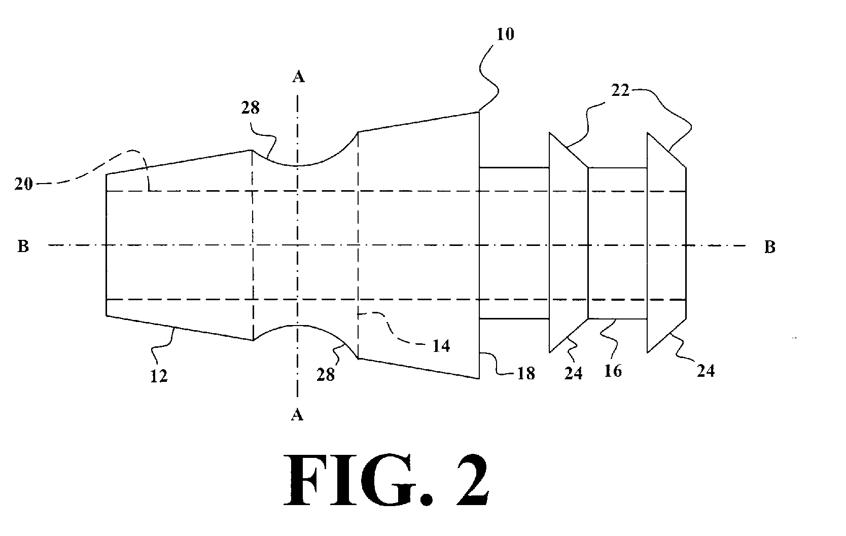
[0066]FIG. 1 is a top plan view of the first preferred embodiment of the invention 10, showing the frustoconical main body 12, through which passes a first cylindrical channel 14. An attachment member 16 extends from the base 18 of the frustoconical main body. The attachment member preferably has a generally cylindrical shape. (Alternatively, the attachment member may have a generally conical or frustoconical shape, or any other suitable shape.) Preferably, the main body and the attachment member share a common axis B-B. There is a second cylindrical channel 20, which passes through the main body and the attachment member, sharing axis B-B, and intersects the first channel. One or more gripping members 22 extend from the outer surface of the attachment member, to enable a lure to be retained on the invention. Preferably, the gripping members are frustoconical flanges, having sides 24 that slope in a direction opposite to the direction that the side 26 of the main body slopes. Altern...


PUM


Abstract

A jig head, to which a fishing lure may be attached, that can pivot on a fish hook or clip to attract fish as it is pulled through the water on a fishing line. There is a channel through the jig head, through which the fish hook or clip is inserted, so that the jig head (and the attached lure) can pivot on the hook or clip. As the fish hook is not permanently attached to the jig head, it will be easy to replace a worn or damaged hook, while reusing the jig head with a new hook. There may be a second channel through the jig head, through which water can flow, to further attract fish by the sound of the water flowing through the jig head and lure, and optionally to help disperse an attractive scent from the lure into the water.

Description

CROSS REFERENCE TO RELATED APPLICATIONS [0001] This application is a Continuation-ln-Part of Regular Utility patent application No. 10 / 856,944, filed on Jun. 4, 2004, which was a Continuation-In-Part of Regular Utility patent application No. 10 / 375,035, filed on Feb. 28, 2003 (now abandoned), which was based on Provisional Patent Application Ser. No. 60 / 361,199, filed on Feb. 28, 2002.BACKGROUND OF THE INVENTION [0002] 1. Field of the Invention [0003] The present invention relates to apparatus used to attract and catch fish. [0004] 2. Description of the Prior Art [0005] In the art of fishing there are devices that are known as jigs, which are usually weighted with lead or steel. Commonly, a hook portion of the jig supports a soft plastic tube bait, live bait, a skirt or other attractant to fish. A problem with the prior art is that the jig head is fixed in an immovable fashion to the hook. This severely limits the swimming or undulating motion available to the attractor portion of t...

Claims


Application Information

Patent Timeline
Patent Type & Authority Applications(United States)
IPC IPC(8): A01K85/00A01K85/01
CPCA01K85/01A01K85/00
Inventor MITCHELL, ALLAN DAVID
Owner MITCHELL ALLAN DAVID
Why Eureka
Try Eureka