Roof membrane fastener, system, and fastening method

Inactive Publication Date: 2005-11-10
MANVILLE JOHNS
View PDF17 Cites 8 Cited by
  • Summary
  • Abstract
  • Description
  • Claims
  • Application Information

AI Technical Summary

Benefits of technology

[0007] The multi-layer roof sheet membrane system and method of the subject invention provide such a solution. The multi-layer roof sheet membrane system and method of the subject invention secure base sheet membranes with self-adhering topside surfaces to a wooden roof deck or other roof substrate with mechanical fastener assemblies: that permit the topside release sheets overlying the self-adhering topside surfaces of the membranes to remain in place until the next layer of the multi-layer roof membrane system is to be installed; that permit the easy and quick removal of the topside release sheets to expose the self-adhering topside surfaces of the base sheet membranes once the overlying layer or layers of a multi-layer roof membrane system are to be installed; and that permit roofers to walk over, kneel on and otherwise make contact with the base sheet membranes and/or overlying layers of a multi-layer roof membrane system after the base sheet membranes have been secured to the roof substrate without degrading the base sheet membranes.
[0008] The multi-layer roof sheet membrane system of the subject invention includes a base sheet membrane with a self-adhering topside surface that is overlaid by a topside release sheet. Preferably, the roof s

Problems solved by technology

However, for certain applications adhering the base sheet membranes directly to a roof deck or other roof substrate is not a preferred means of attachment.
For example, adhering base sheet membranes of a multi-layer roofing system directly to a wooden roof deck presents a problem when the base sheet membranes must be torn off and removed from the deck prior to re-roofing the wooden deck.
It is difficult to tear off and remove these self-adhered base sheet membranes from the wooden deck

Method used


Image

  • Roof membrane fastener, system, and fastening method
  • Roof membrane fastener, system, and fastening method
  • Roof membrane fastener, system, and fastening method

Examples


Example

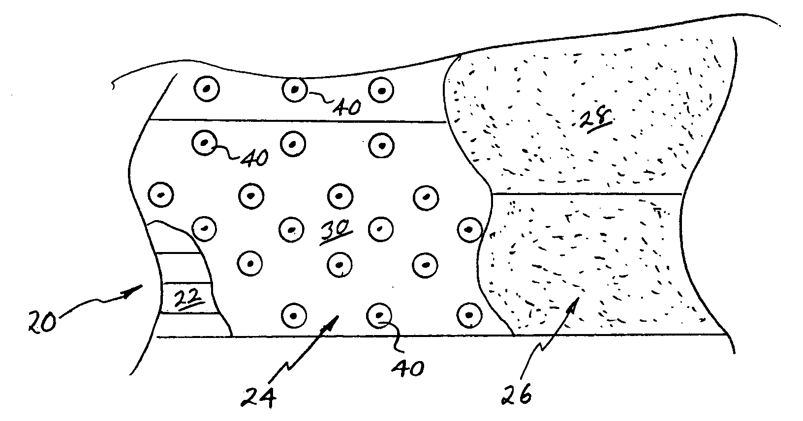
[0018]FIG. 1 shows a partial plan view of an example of a multi-layer roof sheet membrane system of the subject invention 20 installed on a roof substrate 22 with portions of the multi-layer roof sheet membrane system 20 broken away to better show underlying layers of the system. The multi-layer roof sheet membrane system 20 includes a base sheet membrane 24 and a cap sheet membrane 26 with a mineral surfaced topside major surface 28 that is bonded to the base sheet membrane 24 by the asphalt coated self-adhering topside major surface 30 of the base sheet membrane. The base sheet membrane 24 may be a self-adhering topside and bottom side base sheet membrane that preferably has a sheet, sand, or granular layer interposed between the bottom side major surface of the membrane and the roofing substrate 22 to keep the base sheet membrane from adhering to the roofing substrate or the base sheet membrane 24 may be a base sheet membrane with a self-adhering topside major surface and a non-a...


PUM


Abstract

A roof sheet membrane system includes a roof sheet membrane with an adhesive bonding surface that is overlaid by a topside release sheet. The roof sheet membrane is secured to a roof substrate by a plurality of fastener assemblies. Each of the fastener assemblies includes a mechanical fastener passing through the topside release sheet and roof sheet membrane and into the roof substrate to secure the roof sheet membrane to the roof substrate and a disk through which the mechanical fastener passes. The disk contacts and overlays a portion of the topside release sheet immediately surrounding the mechanical fastener and causes the portion of the topside release sheet overlaid by the disk to be easily separable from a remainder of the topside release sheet when the topside release sheet is removed from the roof sheet membrane prior to adhering an overlying roofing layer to the roof sheet membrane.

Description

BACKGROUND OF THE INVENTION [0001] The subject invention relates to a multi-layer roof sheet membrane system, to a method of installing the multi-layer roof sheet membrane system on a roof substrate, and to a roof sheet membrane fastener assembly for securing roof sheet membranes of the system to a roof substrate. More specifically, the subject invention relates to a multi-layer roof sheet membrane system that includes roof sheet membranes with topside adhesive surfaces that are overlaid by topside release sheets that are removed subsequent to securing the roof sheet membranes with mechanical fastener assemblies to a roof substrate. [0002] Certain multi-layer roofing systems utilize base sheet membranes, such as the multi-layer roofing base sheet membranes sold by Johns Manville International, Inc. under the trade designation DynaGrip®, that have self-adhering topside and bottom side surfaces. The topside and bottom side self-adhering surfaces of these multi-layer roofing base sheet...

Claims


Application Information

Patent Timeline
IPC IPC(8): E04B7/02E04D5/02E04D5/14F16B13/04
CPCE04D5/145E04D5/143
Inventor ORTEGA, JEREMY ALAN
Owner MANVILLE JOHNS
Why Eureka
Try Eureka