Eureka AIR delivers breakthrough ideas for toughest innovation challenges, trusted by R&D personnel around the world.

Phase-change valve apparatuses

Inactive Publication Date: 2005-11-10
THE AEROSPACE CORPORATION
View PDF92 Cites 41 Cited by
  • Summary
  • Abstract
  • Description
  • Claims
  • Application Information

AI Technical Summary

Benefits of technology

[0028] Thus, in an example embodiment, a valve apparatus includes a substrate, a main flow channel formed in the substrate, a control channel formed in the substrate such that the main flow channel and the control channel meet at a junction, a bi-phase material within the control channel, a heating element adjacent the control channel and the junction, t

Problems solved by technology

Producing reliable valves has proven to be problematic with all of these devices.
This requires sealing against a valve seat, and often leads to complicated geometries.
In etched solid chips, the valves tend to be very complicated, requiring multiple etching and deposition steps, and such valves suffer from a tendency to leak.
While this method has been shown to work for some applications, there are issues with the large number of pneumatic control lines required for large-scale integrated μTAS devices, as well as with concerns about leakage and the limitations on operating pressure.
A challenge with this type of valve is providing a source and a sink for the phase-change material.
A problem with this method is that the phase-c

Method used


Image

  • Phase-change valve apparatuses
  • Phase-change valve apparatuses
  • Phase-change valve apparatuses

Examples


Example

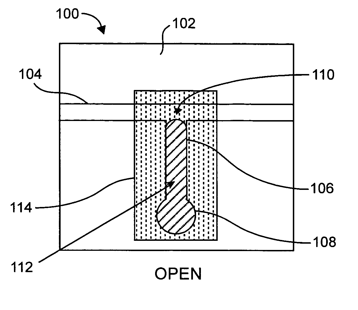
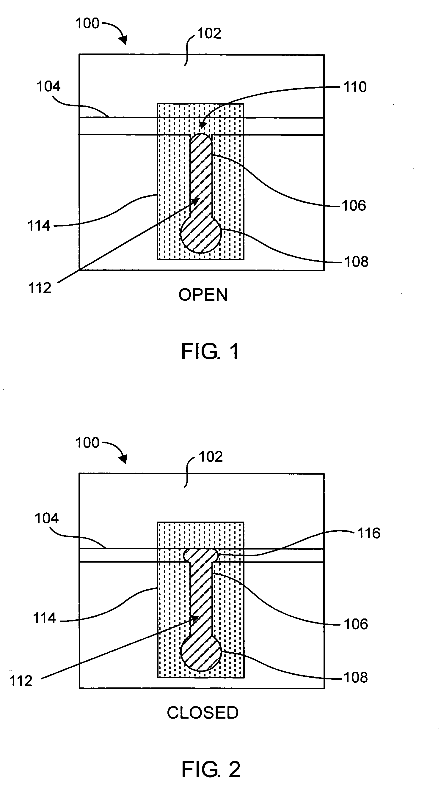
[0019] According to various embodiments of the present invention, an electrically actuated bi-stable valve (e.g., microvalve) uses a phase-change control fluid to alternately block and unblock the flow of a working fluid through the valve. The control fluid is introduced from a side channel, and is pumped into or out of a main flow channel when the control fluid is in a liquid state. Referring to FIG. 1, in an example embodiment, a valve apparatus 100 (shown in its open state) includes a substrate 102 in which are formed a main flow channel 104, a control channel 106 and a reservoir 108 as shown. In this example embodiment, the main flow channel 104 traverses the valve apparatus 100 in a straight, horizontal path, and the control channel 106 provides a path from a junction 110 (between the main flow channel 104 and the control channel 106) to the reservoir 108. In this example, the valve apparatus 100 includes a bi-phase material 112, which is substantially or completely contained w...


PUM


Abstract

A valve apparatus includes a substrate, a main flow channel formed in the substrate, a control channel formed in the substrate such that the main flow channel and the control channel meet at a junction, a bi-phase material within the control channel, a heating element adjacent the control channel and the junction, the heating element being controllable to generate sufficient energy to cause the bi-phase material to transition from a solid phase to a liquid phase, and a pumping mechanism for forcing the bi-phase material either into or out of the junction when the bi-phase material is in the liquid phase.

Description

TECHNICAL FIELD [0001] The invention relates generally to valves for controlling fluid flow and, in particular, to valves for microfluidic devices. BACKGROUND ART [0002] Developments in miniaturization and large-scale integration in fluidics have led to the concept of creating an entire chemistry or biology laboratory on a fluidic analog of the electronic microchip. Such integrated microfluidic devices (known as Micro Total Analysis Systems, or μTAS) are seen as key to automating and reducing costs in many biological analysis applications, including genetic analyses and medical diagnostics. Devices for these applications have been fabricated by etching small glass plates or silicon chips or by injection molding or by hot embossing of either hard or soft polymeric materials. Producing reliable valves has proven to be problematic with all of these devices. [0003] Traditional fluid valves operate by moving solid objects to obstruct the flow path. This requires sealing against a valve s...

Claims


Application Information

Patent Timeline
IPC IPC(8): F15C1/04F15C5/00F16K99/00G05D7/00
CPCB01L3/502738B01L2300/1822B01L2400/0677F15C5/00F16K2099/0084F16K99/0003F16K99/0021F16K99/0044F16K99/0001Y10T137/2196Y10T137/5283Y10T137/2191Y10T137/2224Y10T137/2213
Inventor WELLE, RICHARD P.
Owner THE AEROSPACE CORPORATION
Why Eureka
Eureka Blog
Learn More