Porous coatings bearing ligand arrays and use thereof

a technology of porous coatings and ligand arrays, applied in the direction of sugar derivatives, library creation, and sequential/parallele process reactions, can solve the problems of increasing surface density, requiring costly imaging equipment, and long image acquisition time,

Inactive Publication Date: 2005-10-04
SYNTRIX BIOSYST
View PDF4 Cites 129 Cited by
  • Summary
  • Abstract
  • Description
  • Claims
  • Application Information

AI Technical Summary

Benefits of technology

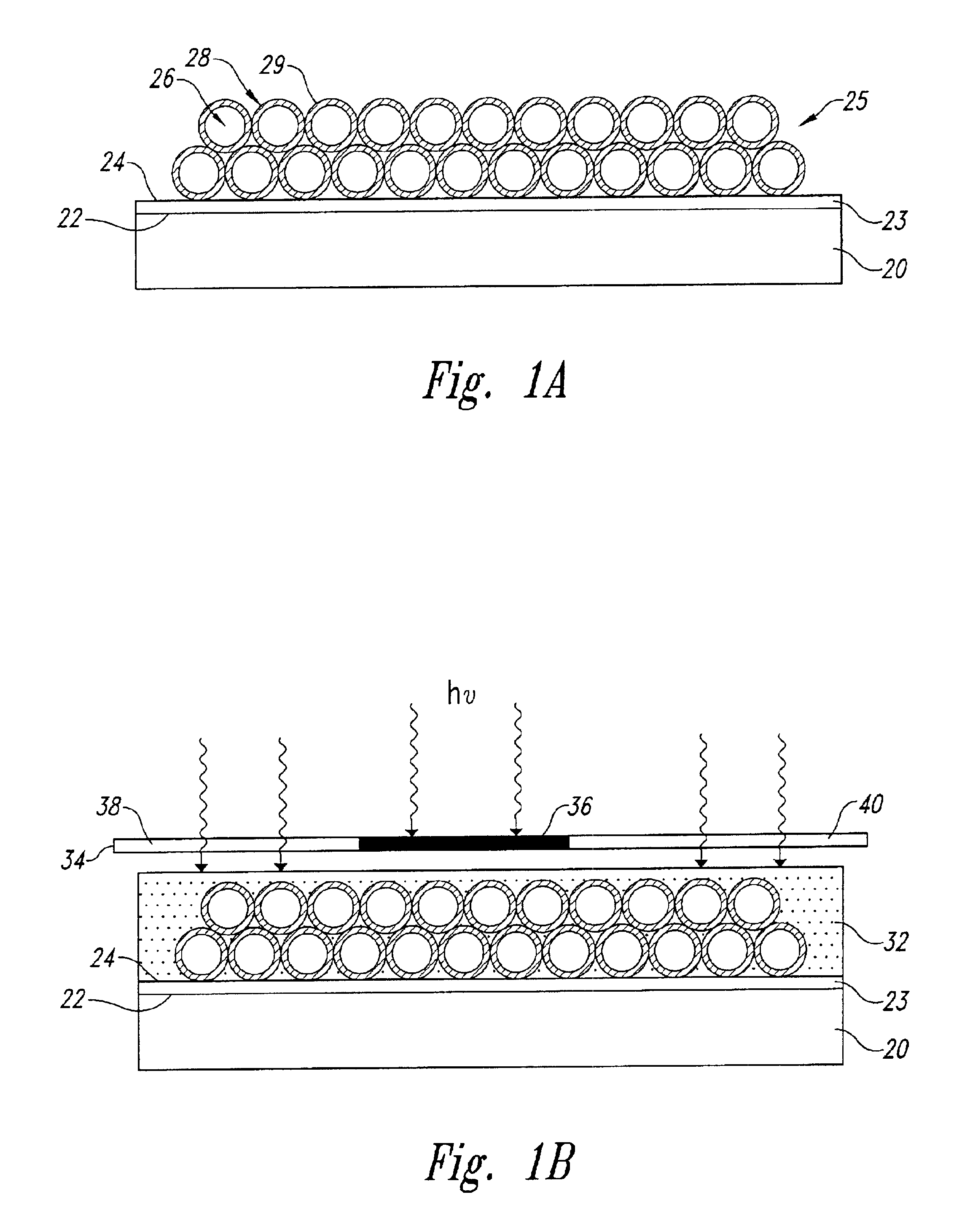
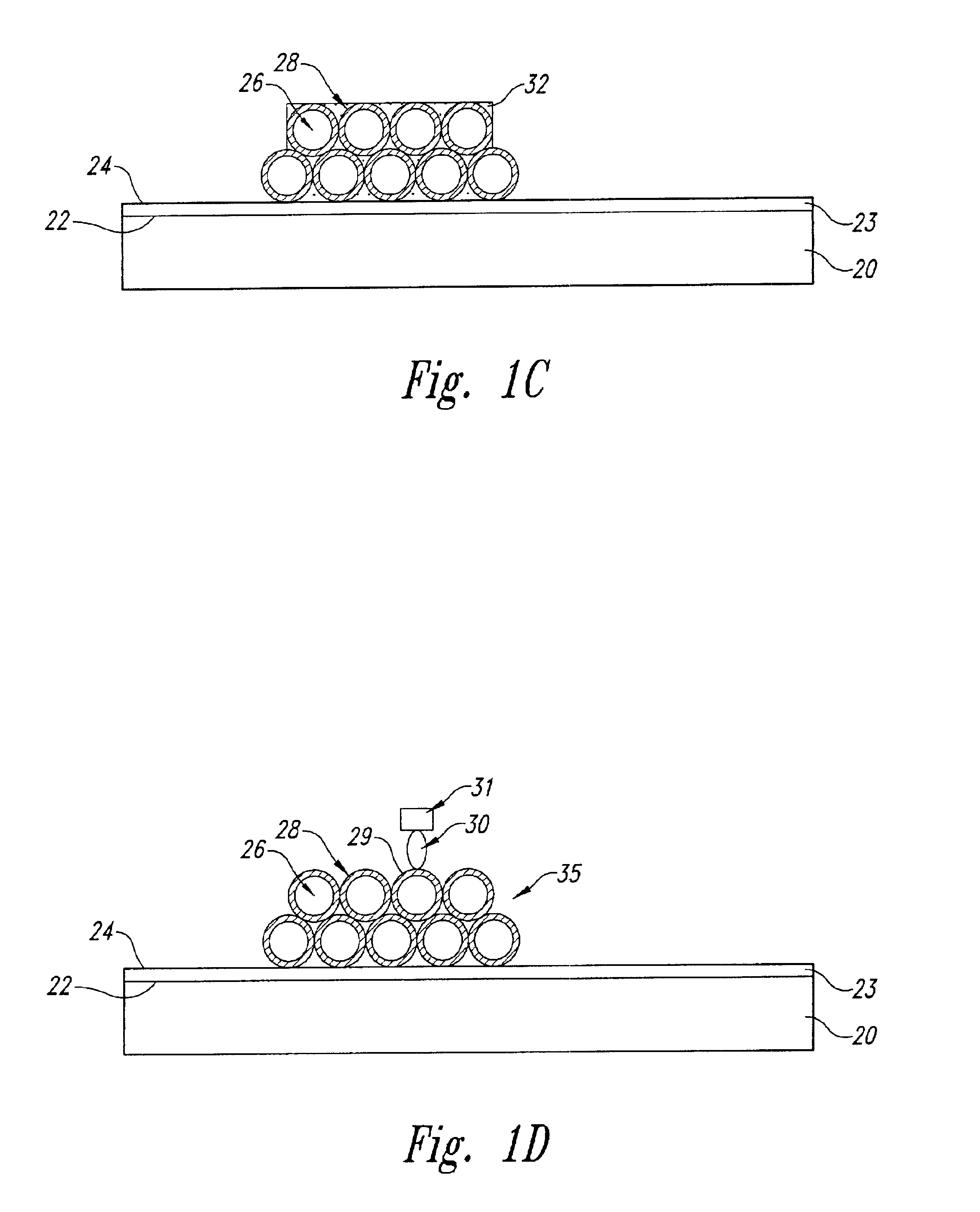
[0013]Briefly stated, the present invention provides articles comprising porous coatings and attached ligands, and methods for preparing and using such articles. Within certain aspects, the present invention provides coated articles comprising a substrate having a continuous porous coating of substantially uniform thickness, wherein the coating comprises a gelled network of particles, and wherein the porous coating has two or more different compounds attached thereto. Suitable particles may comprise one or more of carbon, activated carbon, fluorinated carbon, styrenedivinylbenzene copolymers, pol

Problems solved by technology

However, the surface density of ligand is often low, resulting in the need for costly imaging equipment and long image acquisition times. Drug discovery efforts have been further hampered by low ligand surface density, since many functional assays require higher ligand concentrations to identify drug leads.
Such an approach increases the surface density of the ligands, but places a size restriction on diffusion into the polymer that many receptors exceed.
Furthermore, such polymeric supports may not be compatible with solid-phase chemical synthesis, which requires adequate swelling and salvation of a polymeric matrix in order to achieve efficient mass transfer of reagents.
Further, although this polymer can be photopatterned (i.e., multiple discrete pads may bc generated by a process involving exposure to irradiation), the photosensitivity is severely limited, requiring 30 minutes of illumination.
Such a low throughput is inadequate for mass production.
Existing techniques for increasing ligand density on a solid support provide insufficient surface area enhancement.
Relative to nanoporous materials, a macroporous configuration has inadequate surface area to significantly increase ligand surface density.
Additionally, the parallel pore orientation of these substrates is technically cumbersome, since it requires a flow-through apparatus in order for receptor to bind ligand.
Further, it is unclear whether such substrates could function

Method used


Image

  • Porous coatings bearing ligand arrays and use thereof
  • Porous coatings bearing ligand arrays and use thereof
  • Porous coatings bearing ligand arrays and use thereof

Examples


example 1

Attachment of an Adhesive Layer

[0297]This Example describes the attachment of an adhesive layer to a glass substrate, prior to application of a porous coating.

[0298]An adhesive layer was prepared on a commercial glass microscope slide (Curtin-Matheson Scientific, Inc., Houston, Tex.). The adhesive layer was prepared from a clear sol obtained by hydrolyzing and aging tetraethoxysilane (Aldrich Chemical Company, Inc., Milwaukee, Wis.). To prepare the sol, a concentrated sol was first prepared by hydrolyzing 21.7 ml of tetraethoxysilane in 6.3 ml H2O and 0.7 ml IN nitric acid at room temperature for approximately 1 hour, followed by aging at 4° C. for several days. The concentrated sol was diluted 50-fold with ethanol, and applied to one surface of the slide at an incline using a pipette. The solvent was allowed to evaporate at room temperature leaving an adhesive layer less than 1 μm thick, and a free adhesive surface. The layer was cured by placing the slide on a heating block at 110...

examples 2-8

Preparation of Representative Porous Coatings

[0299]These Examples describe the preparation of representative porous coatings.

[0300]The porous coating was obtained from a liquid coating solution. The coating solutions were prepared as follows: Five grams of fumed silica (SiO2) with a primary particle size of 500 Å (Degussa, Inc., Ridgefield Park, NJ) were dispersed in 100 ml of 95% ethanol (5% water). To this dispersion was added tetraethoxysilane (TEOS) monomer or polymer in an amount indicated in Table VIII. TEOS polymer was obtained as described in Example 1. Sufficient nitric acid was added to provide an acidity of from 2.0 to 4.2 pH units. Coating solutions that incorporated linker molecules further included 3-aminopropyltriethoxysilane (i.e., “APES”, from Aldrich Chemical Company, Inc., Milwaukee, Wis.) or bis(2-hydroxyethyl)-3-aminopropyltriethoxysilane (i.e., “HAPES”, from Gelest, Inc., Tullytown, Pa.) in amounts as indicated in Table VIII. The coating solutions thus formed w...

examples 9-18

Comparative Coatings

[0303]These Examples illustrate the preparation of coatings in a manner similar to those in Examples 2-8, with modifications as summarized in Table IX. The coating solutions were applied to the adhesive surface of glass slides prepared as in Example 1, producing substantially uniform liquid layers. The liquid layers were allowed to evaporate at room temperature followed by curing at 120° C. for 15 minutes. The series of coatings were evaluated with respect to film quality as reported in Table IX.

[0304]

TABLE IXLinker,ExampleTEOS,TEOSμmole / gAge ofMajorityFilmNumberμmole / g silicapolymerizedsilicapHMixSolventQuality9————NAethanolseparated10————NAwatercracked11————NA3-pentanoneseparated121860no—2.8 3-pentanoneflocculated13744yes—4.2 ethanolseparated14240no—>10>24 hrsethanolclumped15——APES, 604.1>24 hrsethanolflocculated16180noHAPES, 604.0>24 hrsethanolclumped17180yesAPES, 604.1>24 hrsethanolclumped18180noAPES, 604.2  18 hrsethanolseparated1NA - not applicable.

[0305]A...


PUM

PropertyMeasurementUnit
Temperatureaaaaaaaaaa
Fractionaaaaaaaaaa

Abstract

Articles comprising substantially uniform porous coatings, which may be photopatterned, are provided. The use of such porous coatings increases the surface density of attached compounds within, for example, ligand arrays prepared by methods such as regionally selective solid-phase chemical synthesis. Arrays prepared using the porous coatings may be used within a variety of diagnostic and drug discovery assays.

Description

CROSS REFERENCE TO RELATED APPLICATIONS[0001]This Application claims the benefit of U.S. Provisional Application No. 60 / 110,529, filed Dec. 1, 1998.TECHNICAL FIELD[0002]The present invention relates generally to articles comprising porous coatings, and to methods for preparing and using such articles. The invention is more particularly related to methods for fabricating articles having patterned porous coatings, which may be used, for example, to screen large numbers of discrete compounds for diagnostic or drug discovery purposes.BACKGROUND OF THE INVENTION[0003]Receptor-ligand interactions are critical components of many fundamental biological processes. Such interactions involve specific binding of a macromolecule receptor (e.g., enzyme, cell-surface protein, antibody or oligonucleotide) to a particular ligand molecule. Receptor-ligand binding may affect any of a variety of intercellular and intracellular processes in an organism, such as signal transduction, gene expression, immu...

Claims


Application Information

Patent Timeline
IPC IPC(8): B01J19/00C07B61/00C03C17/00C07H21/00C07K5/02C07K5/00C12Q1/68C12Q1/37G01N33/551G01N33/552G01N33/543C12M1/00C12M1/34C12N15/09C40B40/06C40B40/10C40B50/14C40B60/14G01N33/15G01N33/50G03F7/004
CPCB01J19/0046B82Y30/00C03C17/007C03C17/009C07H21/00C07K5/0222C12Q1/37C12Q1/6809C12Q1/6841G01N33/552B01J2219/00432B01J2219/00497B01J2219/005B01J2219/00527B01J2219/00529B01J2219/00585B01J2219/0059B01J2219/00596B01J2219/00605B01J2219/00612B01J2219/00617B01J2219/00621B01J2219/00626B01J2219/00637B01J2219/00644B01J2219/00648B01J2219/00659B01J2219/00675B01J2219/00702B01J2219/00711B01J2219/0072B01J2219/00722B01J2219/00725B01J2219/00729C03C2217/425C03C2217/475C07B2200/11C12Q1/6837C40B40/06C40B40/10C40B50/14C40B60/14G01N2333/96486Y10T428/249982Y10T428/249967Y10T428/24997Y10T428/249979
Inventor ZEBALA, JOHN A.
Owner SYNTRIX BIOSYST
Why Eureka
Try Eureka