Header pipe evaporator for use in an automobile

a technology for evaporators and header pipes, which is applied in the direction of indirect heat exchangers, refrigeration components, light and heating apparatus, etc., can solve the problems of increasing reducing the efficiency of evaporators, and increasing the risk of reducing the evaporator's performance, so as to reduce the number of assembly processes, reduce the risk of refrigerant leakage, and reduce the number of assembling processes

Inactive Publication Date: 2005-11-10
MODINE KOREA
View PDF19 Cites 33 Cited by
  • Summary
  • Abstract
  • Description
  • Claims
  • Application Information

AI Technical Summary

Benefits of technology

[0005] The present invention is designed to solve the problems as described above, therefore the objective is to decrease the number of assembling processes with regard to the individual parts being constituents of

Problems solved by technology

However, before such brazing process is applied to each part, the assembly of the parts has to be completed and thus the number of assembly processes is increased, which negatively affects productivity and raises costs.
In addition, if there

Method used


Image

  • Header pipe evaporator for use in an automobile
  • Header pipe evaporator for use in an automobile
  • Header pipe evaporator for use in an automobile

Examples


Embodiment Construction

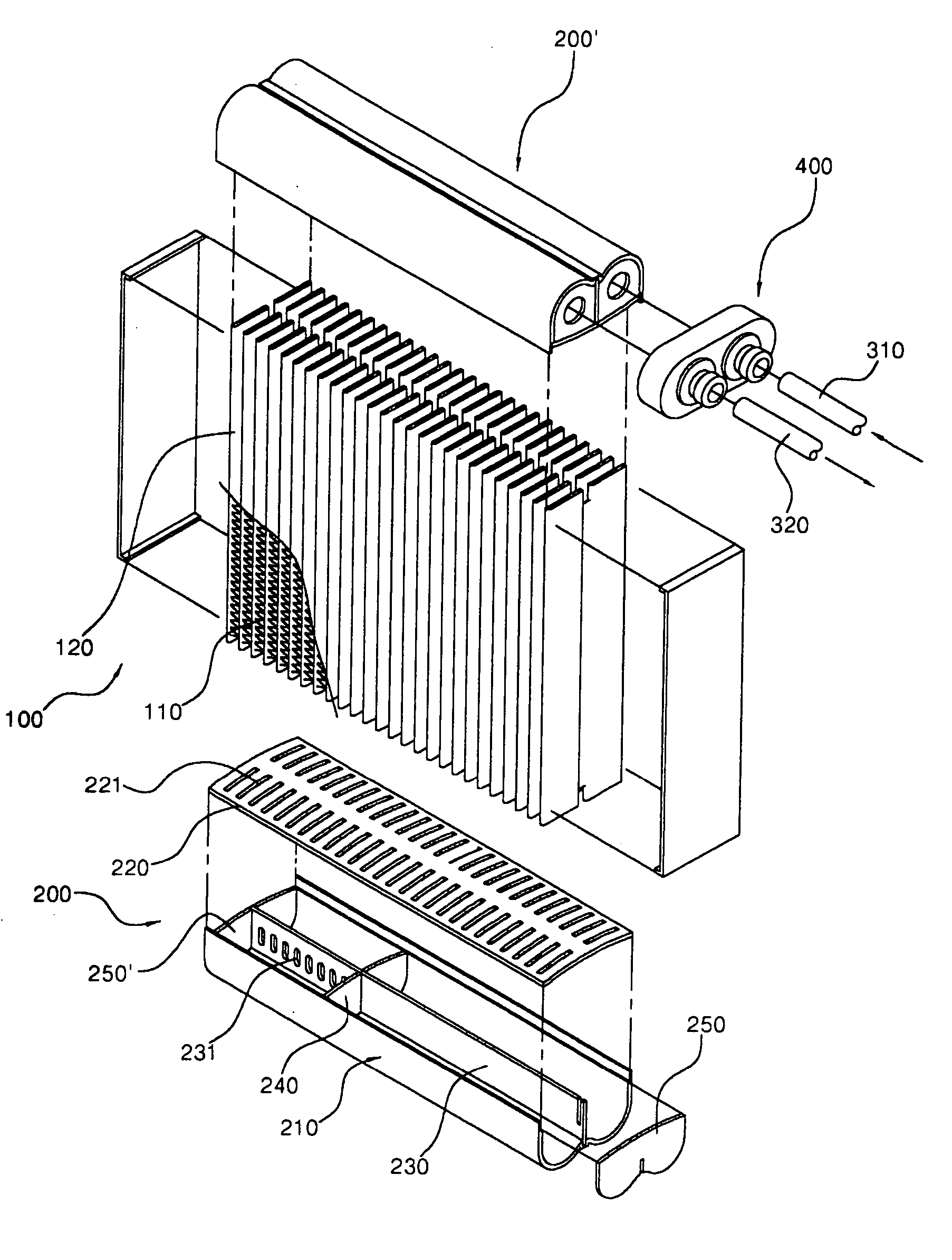
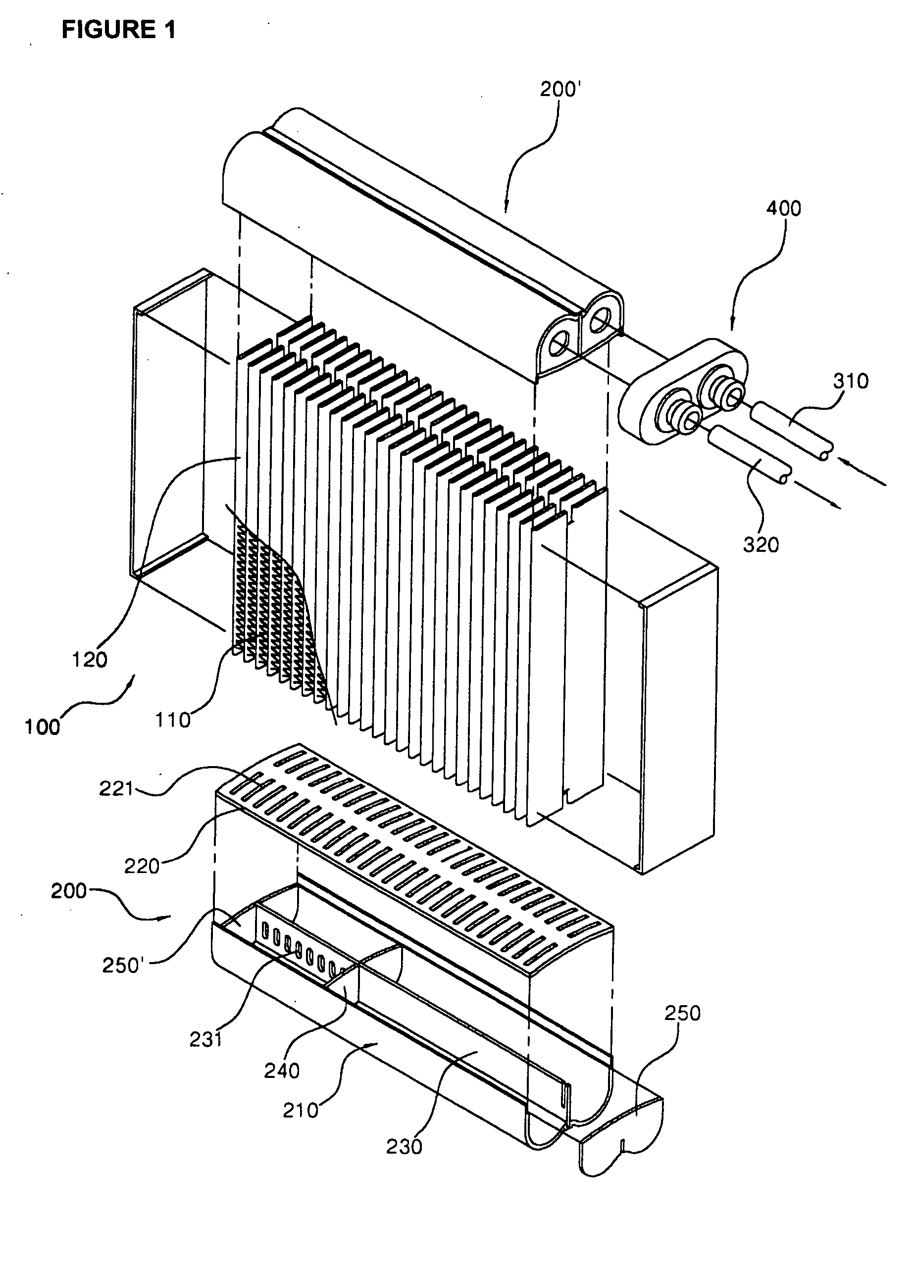
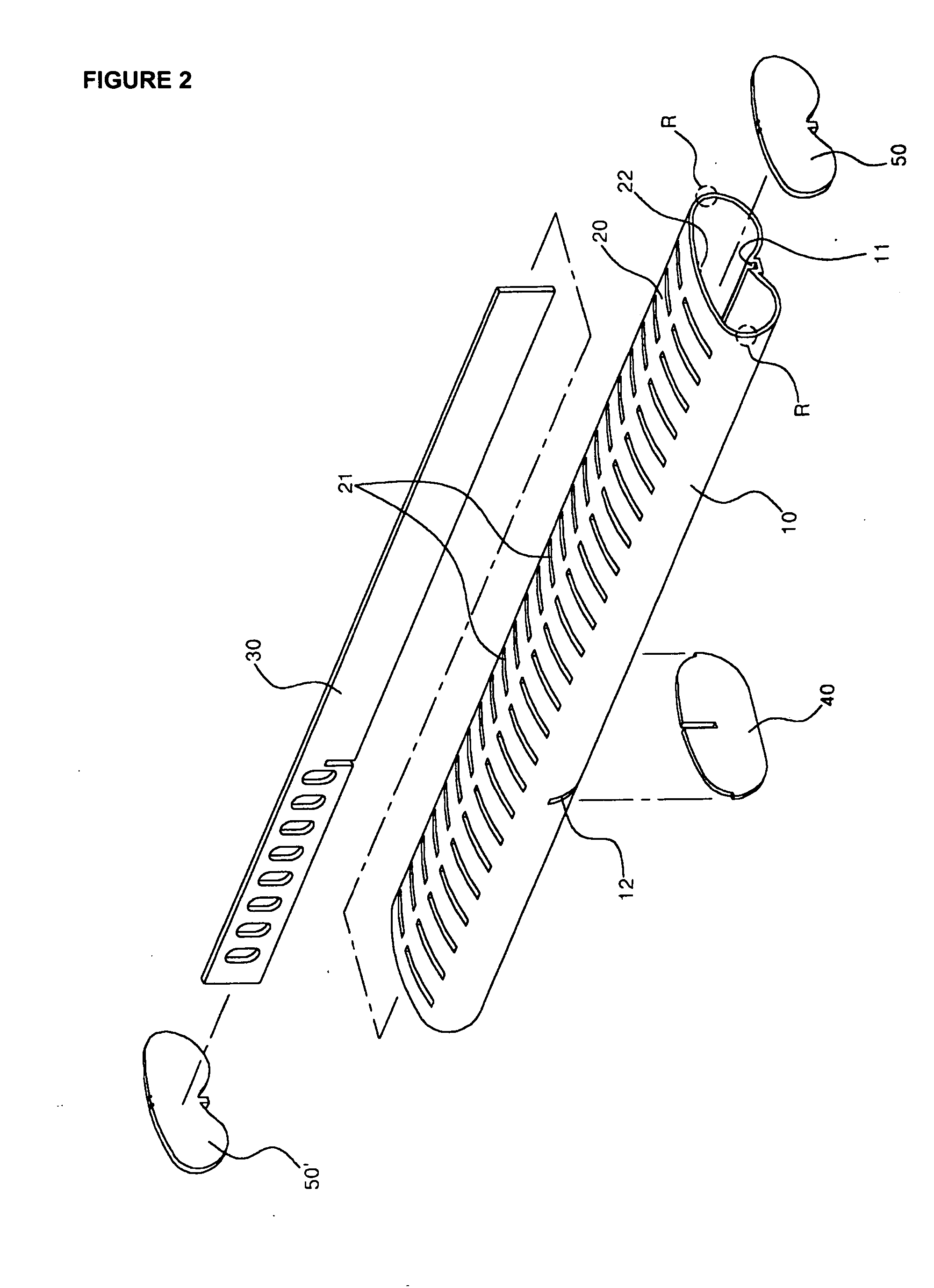
[0018] The attached FIG. 2, FIG. 4, and FIG. 5 present, respectively, this invention's header pipe appearance in a perspective view of separate parts, assembling perspective view, and a perspective view of a nearly completed assembly; while FIGS. 3 and 6 present perspective views of the right-side end portions of FIGS. 2 and 5, respectively.

[0019] As shown on the illustrations, this invention's header pipe is realized, wherein the tank part (10) having the refrigerant flow path space where the refrigerant flows, and the header part (20) form a tube body, the header part (20) covering the tank part (10)'s flow path space and having numerous through-holes (21) for connecting the end portions of the refrigerant tubes (not shown); the tank part (10) and the header part (20) are formed into an integral structure by extrusion or other method. In particular, by forming a rounding portion (R) at the connecting portion of the tank part (10) and the header part (20), joined into an integral ...


PUM


Abstract

The present invention relates to a header pipe for a vehicle evaporator capable of decreasing the number of assembling processes of a header pipe and minimizing/preventing a refrigerant leakage at a junction portion after elements are brazed for thereby achieving a simpler construction. In the present invention, a vehicle evaporator is provided with a header pipe, comprising a tank part and a header part forming an integral structure wherein a partition wall partitioning a refrigerant flow path space of the tank part, a partition plate for changing a refrigerant flow path at the tank part, and caps for covering the openings of both sides of the tank part are assembled in a structure.

Description

FIELD OF THE INVENTION [0001] The present invention applies to the technology of an evaporator being a constituent of an air conditioning system for use in an automobile, and more precisely—to a header pipe used at the connection point with the end portion of a tube through which the refrigerant flows in an evaporator. BACKGROUND OF THE INVENTION [0002] The present invention applies to the technology of an evaporator being a constituent of an air conditioning system for use in an automobile, and more precisely—to a header pipe used at the connection point with the end portion(s) of a tube(s) through which the refrigerant flows in an evaporator. [0003] An evaporator, being a commonly used constituent of an air conditioning system for use in an automobile, wherein numerous tubes through which the refrigerant flows, and heat transfer fins form its core, and each tube's end part connects through the header pipe into a structure. [0004] The attached FIG. 1 illustrates an example of the a...

Claims


Application Information

Patent Timeline
IPC IPC(8): F25B39/02F28D1/053F28F9/02
CPCF28D1/05391F28F2220/00F28F9/0207F25B39/028E05B17/18
Inventor KIM, JAE HOON
Owner MODINE KOREA
Why Eureka
Try Eureka