System and methods for determining nonuniformity correction parameters in detector-array imaging

a detector array and correction parameter technology, applied in the field of imaging systems, can solve the problems of spacial non-uniformity, reduce the resolving capability of the imaging system, and the quality of the resulting images obtained with the detector array imaging system, and achieve the effect of strong robustness to outliers and faster and more efficien

Inactive Publication Date: 2005-11-10
SIEMENS ENERGY INC +1
View PDF6 Cites 34 Cited by
  • Summary
  • Abstract
  • Description
  • Claims
  • Application Information

AI Technical Summary

Benefits of technology

[0018] As explained more particularly in the following discussion, the procedures effected by the system and methods of the present invention are based upon statistics-based manipulations, the requirements of which are less constraining than the constant-statistics and constant-range assumptions underlying conventional approaches. The procedure effected by the present invention, accordingly, is not only more faster and more efficient, but can be used a wider variety of situations in more diverse contexts.
[0019] More particularly, with the present invention, neither the mean nor the variance of the image samples taken at each array element needs to be constant, nor does the range of the irradiance. It is still beneficial, however, that the training sequence provides some diversity in the irradiance for every pixel. Additionally, with the present invention, a lens adjacent a detector array may be intentionally out of focus while recording the test sequence to provide blurred images. The sequence may include relatively few different images in a random order as no motion information is exploited. Finally one beneficial new feature of the out of focus algorithm is its strong robustness to outliers, which are very common in real infrared (IR) systems.

Problems solved by technology

An inherent limitation on the quality of the resulting images obtained with detector-array imaging systems is spacial nonuniformity in the photoresponse of the detectors in the array, especially when operating in the infrared (IR) domain.
The effect is fixed-pattern noise that is superimposed on the true image and that reduces the resolving capability of the imaging system.
Additionally, the nonuniformity slowly and randomly drifts over time, which makes solving the problem permanently with an initial calibration of the system very difficult if not impossible.
Moreover, because of manufacturing constraints and varied environmental conditions, the individual detectors of a detector array frequently fail to have identical operating characteristics.
Spatial non-uniformity between detectors may be caused by one or more of the following factors: fixed pattern noise that includes individual detector offsets, residual gain error in the detectors, fixed pattern electronic noise, and / or non-dithered optical structure in the detectors field of view.
These algebraic approaches, however, generally only correct for offsets.
Factory-based calibration, however, generally suffers from multiple drawbacks.
First, the pixel offset errors may not be linearly dependent; rather they may have non-linear temperature variations.
Second, this proposed solution typically cannot correct for short-term temporal variations in pixel offset error that occur during operation of the array.
First, by requiring a means for alternately exposing the array to the observed image and to a signal of known intensity, additional complex mechanical or optical elements are typically necessary.
Second, by requiring that the focal plane array spend time viewing a signal of known intensity instead of the scene under observation, this solution almost inevitably degrades the array's ability to track fast moving objects and reduces the potential signal to noise ratio of the sensor output.

Method used


Image

  • System and methods for determining nonuniformity correction parameters in detector-array imaging
  • System and methods for determining nonuniformity correction parameters in detector-array imaging
  • System and methods for determining nonuniformity correction parameters in detector-array imaging

Examples


Embodiment Construction

[0029] The present invention is more particularly described in the following description and examples that are intended to be illustrative only since numerous modifications and variations therein will be apparent to those skilled in the art. As used in the specification and in the claims, the singular form “a,”“an,” and “the” may include plural referents unless the context clearly dictates otherwise. As used in the specification and in the claims, the term “comprising” may include the embodiments “consisting of” and “consisting essentially of.”

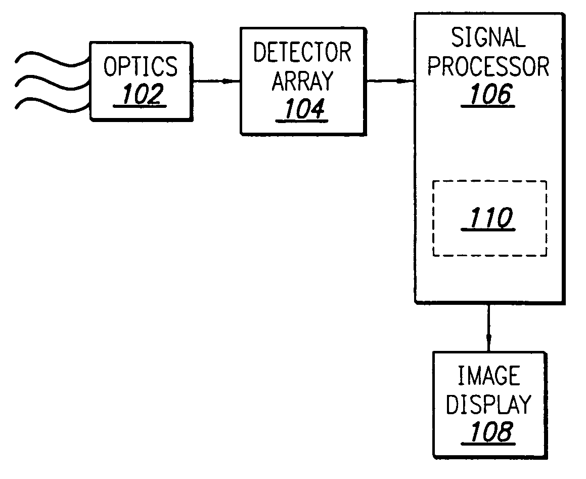
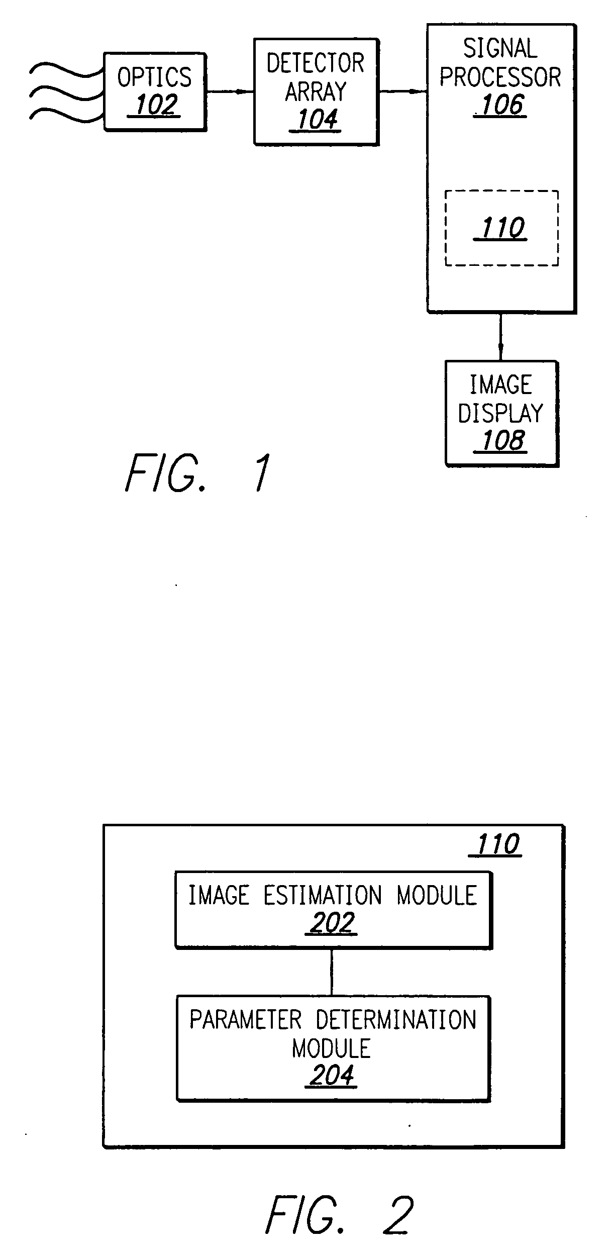
[0030]FIG. 1 provides a schematic diagram of an exemplary operative environment 100 in which an imaging system according to one embodiment of the present invention can be used. The operative environment 100 illustratively includes an optical device 102 and, adjacent to the optical device, a detector array 104. Additionally, the operative environment 100 illustratively includes a signal processor 106 in electrical communication with the detecto...


PUM

PropertyMeasurementUnit
damping coefficientsaaaaaaaaaa
energyaaaaaaaaaa
electricalaaaaaaaaaa

Abstract

An imaging system (110) for imaging a scene with a detector array (104) having an array of imaging elements is provided. The imaging system (110) includes an image estimation module (202) for generating a plurality estimates of uncorrupted images based upon a plurality of noisy images generated by the detector array (104). The imaging system (110) further includes a parameter determination module (204) for determining one or more nonuniformity correction parameters based upon the estimates of uncorrupted images.

Description

CROSS REFERENCE TO RELATED APPLICATIONS [0001] This application claims priority to U.S. Provisional Patent Application No. 60 / 568,523, which was filed May 6, 2004, and to U.S. Provisional Patent Application No. 60 / 568,524, which also was filed May 6, 2004.FIELD OF THE INVENTION [0002] The present invention is directed to imaging systems, and, more particularly, to detector-array imaging. BACKGROUND OF THE INVENTION [0003] A detector array is a combination of individual detectors that are typically arranged in a lattice-like array. The individual detectors of the array are often referred to as the array elements or pixels—a short-hand phrase for picture elements. Each pixel converts the energy from infrared or other electromagnetic (em) radiation into electrical signals. Various techniques for processing these electrical signals often involve quantizing the electrical signals so that they can be represented in digital form. [0004] An example of a detector array is the focal-plane arr...

Claims


Application Information

Patent Timeline
Patent Type & Authority Applications(United States)
IPC IPC(8): A61B6/00G01D18/00G01N23/00G12B13/00G21K1/12H05G1/60
CPCH04N5/33H04N5/367H04N5/3656H04N25/674H04N25/68
Inventor VOLGT, MATTHLASZARZYCKL, MARTLNBRUMMEL, HANS-GERDLEMIEUX, DENNIS H.RAMESH, VISVANATHAN
Owner SIEMENS ENERGY INC
Why Eureka
Try Eureka