Optical engine apparatus

Inactive Publication Date: 2005-11-10
SAMSUNG ELECTRONICS CO LTD
View PDF3 Cites 3 Cited by
  • Summary
  • Abstract
  • Description
  • Claims
  • Application Information

AI Technical Summary

Benefits of technology

[0009] In order to solve the foregoing and / or other problems, it is an aspect of the present general inventive concept to provide an optical engine apparatus to minimize loss of light generated from a light source and projected to a display device, and to improve brightness an image formed by the projected light.
[0010] According to another aspect of the present general inventive concept, an optical path transformation unit is accommodated in an accommodation casing to minimize leaking of the light to thereby maintain a good quality of the image and protect the optical engine apparatus from contamination due to dust or foreign substances.

Problems solved by technology

However, in such a conventional optical engine assembly, the foregoing configurations (components) are assembled into the optical path transformation unit, but fixed to respectively separate positions, thereby causing problems of degrading quality of the light because the light leaks outside, and decreasing quantity of the light since dust and foreign substance adhere to the components and darken the screen.

Method used


Image

  • Optical engine apparatus
  • Optical engine apparatus
  • Optical engine apparatus

Examples


Embodiment Construction

[0024] Reference will now be made in detail to the embodiments of the present invention, examples of which are illustrated in the accompanying drawings, wherein like reference numerals refer to like elements throughout. The embodiments are described below in order to explain the present invention by referring to the figures.

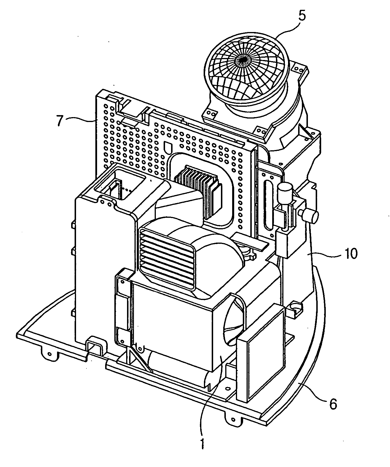
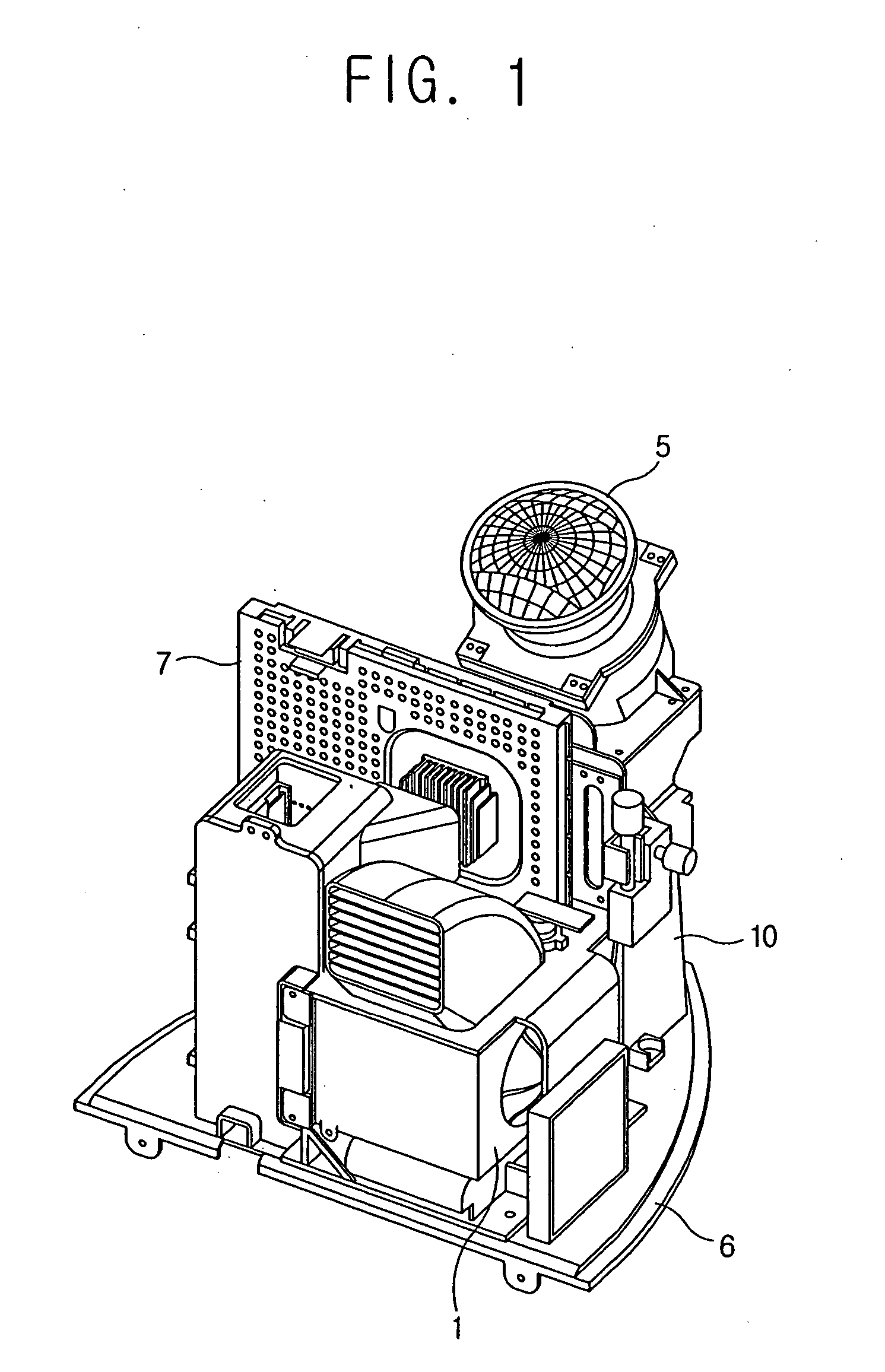
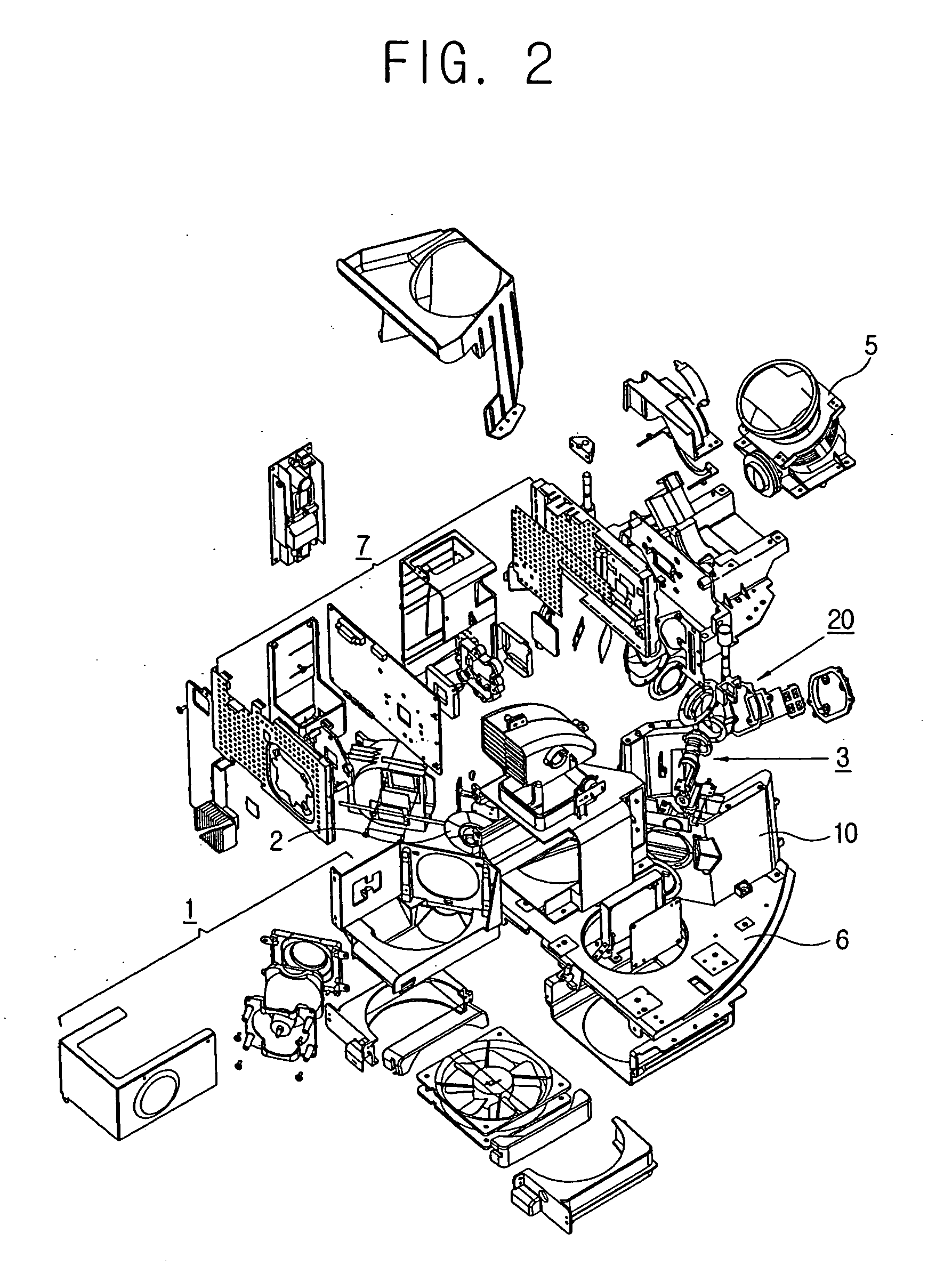
[0025] As shown in FIGS. 1 and 2, an optical engine apparatus may comprise a light source 1 to generate light, a DMD panel 7 used as a display device on which the light emitted from the light source 1 is projected to form an image beam, and a projector 5 to magnify and project the image beam generated by the display device 7 to a screen of a projection television.

[0026] Further, the optical engine apparatus may comprise a color wheel assembly 2 having a color wheel to selectively sort the light from the light source 1 into red (R), green (G) and blue (B) light a light tunnel assembly 3 having a light tunnel used as a uniform light generator to make the light be...


PUM


Abstract

An optical engine apparatus to magnify and project an image beam formed by a display device on a screen includes a light source to emit light, an optical path transformation unit provided on an optical path between the light source and the display device to transform a path of the light from the light source toward the display device, and an accommodating unit in which the optical path transformation unit is accommodated, to form the path of the light in the optical path transformation unit. With this configuration, the optical engine apparatus minimizes a loss of the light generated from the light source and projected to the display device, and improves a brightness of a picture corresponding to the image beam. The optical path transformation unit is accommodated in an accommodation casing to minimize leaking of the light thereby maintaining a good quality of the picture and protecting the optical engine apparatus from contamination due to dust or foreign substances.

Description

CROSS-REFERENCE TO RELATED APPLICATIONS [0001] This application claims the benefit of Korean Patent Application No. 2004-32513 filed on May 8, 2004 in the Korean Intellectual Property Office, the disclosure of which is incorporated herein in its entirety and by reference. BACKGROUND OF THE INVENTION [0002] 1. Field of the Invention [0003] The present general inventive concept relates to an optical engine apparatus used with a projection apparatus, and more particularly, to an optical engine apparatus to minimize loss of light generated from a light source and projected to a display device. [0004] 2. Description of the Related Art [0005] An optical engine apparatus projects light emitted from a light source toward a display device, such as liquid crystal display (LCD) or digital micro-mirror display (DMD), so as to form an image beam, and displays a picture on a screen by magnifying and projecting the image beam onto the screen. [0006] As an example of the optical engine apparatus, a...

Claims


Application Information

Patent Timeline
IPC IPC(8): H04N5/74H04N5/64H04N9/31
CPCH04N9/3197H04N9/3141H04N5/74
Inventor JANG, KYOUNG-CHOUL
Owner SAMSUNG ELECTRONICS CO LTD
Why Eureka
Try Eureka