Pickup guiding structure for optical disk drive

a technology of optical disk drives and guiding structures, which is applied in the direction of disposing/mounting heads, data recording, instruments, etc., can solve the problems of increasing the total increasing the defect rate due to assembly tolerance, and increasing the number of parts of the optical disk drive. , the effect of minimizing the change in the installation state of the optical pickup during us

Inactive Publication Date: 2005-11-10
LG ELECTRONICS INC
View PDF4 Cites 2 Cited by
  • Summary
  • Abstract
  • Description
  • Claims
  • Application Information

AI Technical Summary

Benefits of technology

[0010] Another object of the present invention is to provide an optical pickup guiding structure for an optical disk drive, wherein the assembly tolerance is minimized and the assembly state is changed relatively less during use.
[0014] More preferably, at least one end of the molded guide portion is provided with an elastically deformable stopper, thereby preventing the optical pickup from being inadvertently detached from the pickup base.
[0017] More preferably, at least one end of the molded guide portion is provided with an elastically deformable stopper, thereby preventing the optical pickup from being inadvertently detached from the pickup base.
[0021] More preferably, at least one end of the molded guide portion is provided with an elastically deformable stopper, thereby preventing the optical pickup from being inadvertently detached from the pickup base.
[0023] According to the present invention so configured, there are advantages in that the number of parts of the optical disk drive is minimized, and the change in the installation state of the optical pickup is minimized during use, so that the operational reliability is improved.

Problems solved by technology

However, the aforementioned prior art has the following problems.
Since the respective guide shafts 6 and 6′ are separately manufactured and installed on the pickup base 1, there are problems in that the total number of parts of the optical disk drive is increased and an assembly process thereof is complicated.
Particularly, as the number of parts of the optical disk drive according to the prior art is relatively large, the defect rates due to the assembly tolerance are increased.
There are also problems in that the installation state of the guide shafts 6 and 6′ is changed by an external force during use, and thus, the operational reliability thereof is deteriorated.

Method used


Image

  • Pickup guiding structure for optical disk drive
  • Pickup guiding structure for optical disk drive
  • Pickup guiding structure for optical disk drive

Examples


Embodiment Construction

[0033] Hereinafter, preferred embodiments of an optical pickup guiding structure of an optical disk drive according to the present invention will be described in detail with reference to the accompanying drawings.

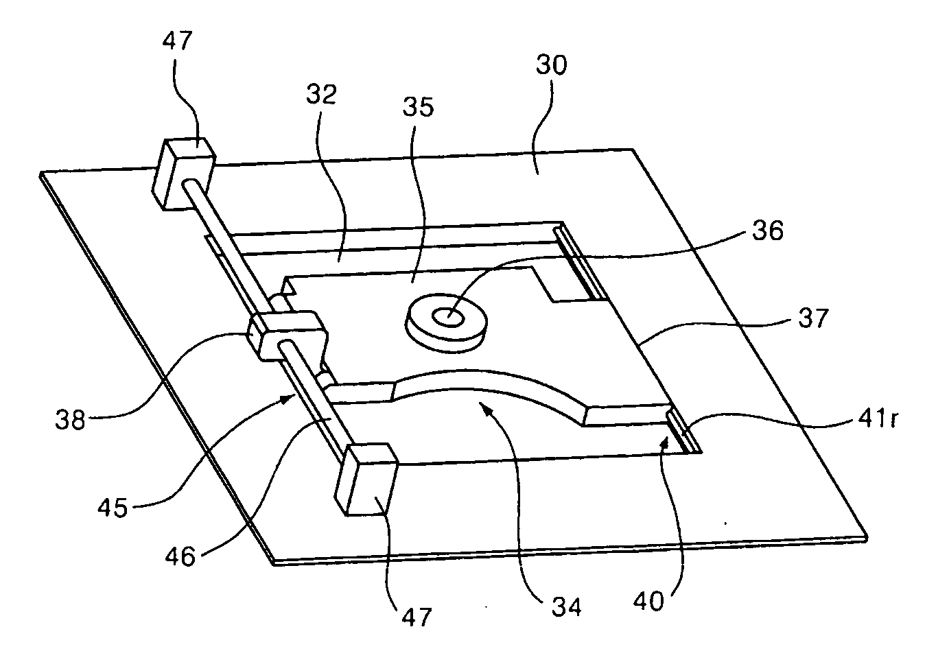
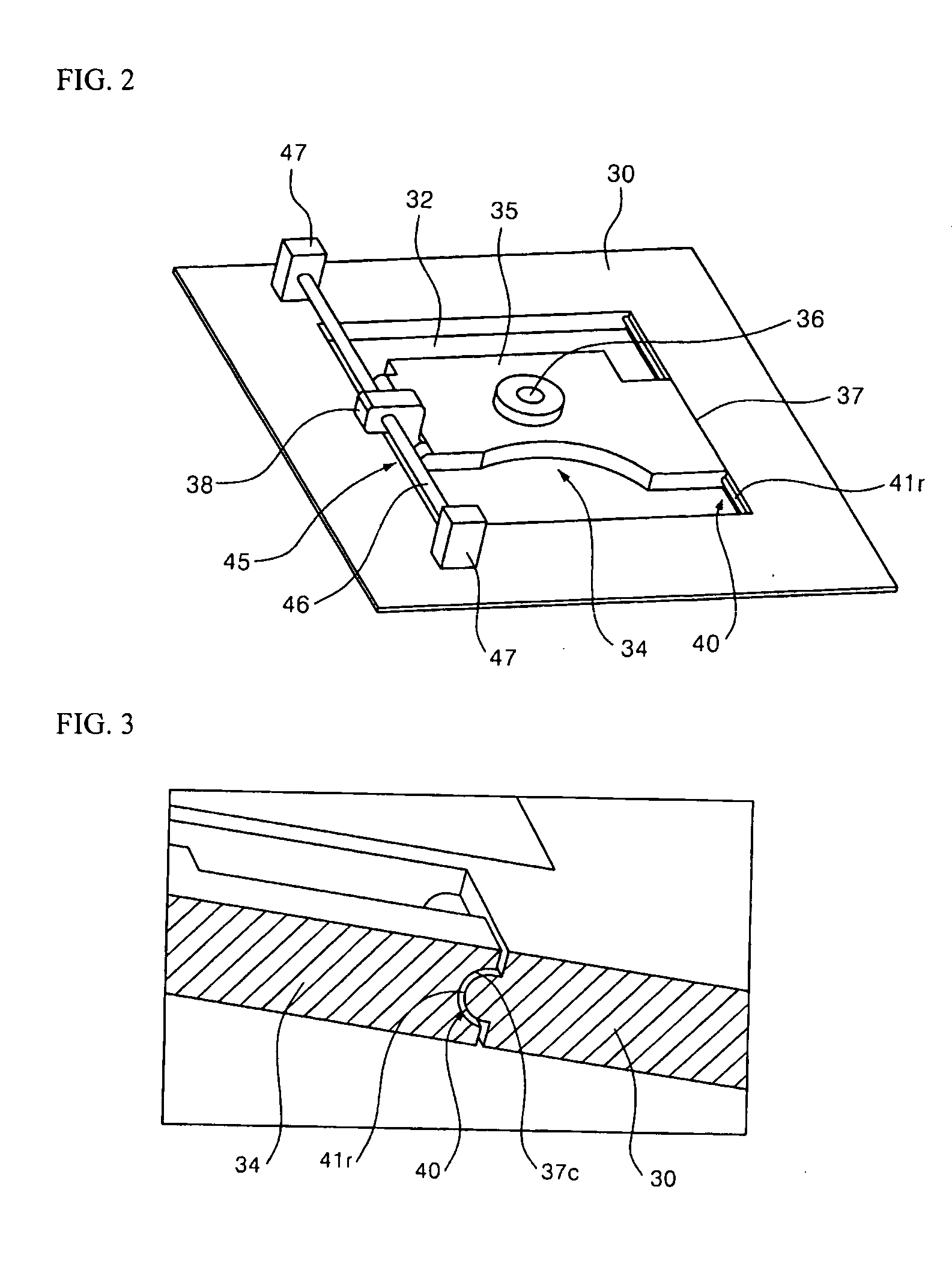
[0034]FIG. 2 is a schematic perspective view showing a preferred embodiment of the optical pickup guiding structure according to the present invention, and FIG. 3 is a sectional perspective view showing the major configuration of the embodiment shown in FIG. 2.

[0035] Referring to the figures, in the present embodiment, a pickup base 30 is installed on a main chassis (not shown) of the optical disk drive. The pickup base 30 is mounted with a spindle motor for rotating a disk, an optical pickup 34 for writing a signal on the disk and reading a recorded signal from the disk, and the like.

[0036] It is preferred that the pickup base 30 be formed of metallic material. In particular, some parts made of synthetic resin may be integrally formed on a portion of the pickup base 30 ...


PUM


Abstract

The present invention relates to an optical pickup guiding structure for an optical disk drive. The structure of the present invention comprises a pickup base 30 with a pickup window 32 formed therein, and an optical pickup 34 that is provided in the pickup window 32 and includes at least one end movably supported by a molded structure integrally formed on the pickup base 30. The end of the optical pickup and a molded structure for movably supporting the end of the optical pickup 34 are formed with a guide channel 37c and a guide rib 41r, respectively, which are complementary to each other, thereby guiding the optical pickup. According to the present invention, there are advantages in that the number of parts of the optical disk drive is minimized, and the change in the installation state of the optical pickup is minimized during use, so that the operational reliability is improved.

Description

BACKGROUND OF THE INVENTION [0001] 1. Field of Invention [0002] The present invention relates to an optical disk drive, and more particularly, to an optical pickup guiding structure for guiding an optical pickup for reading and writing signals from and to an optical disk. [0003] 2. Description of the Prior Art [0004]FIG. 1 is a plan view showing a general optical disk drive. As shown in the figure, a pickup base 1 installed on a main chassis (not shown) is mounted with a spindle motor 2 for rotating a disk D, and the spindle motor 2 is mounted with a turntable 3 on which the disk D is seated. [0005] An optical pickup 5 for writing a signal to a signal recording surface of the disk D or reading the recorded signal from the disk is supported on a pair of guide shafts 6 and 6′, which are installed on the pickup base 1 to be parallel with each other, so that the optical pickup 5 is movable in the radial direction of the disk D. The optical pickup 5 is mounted with a feed guide 7 at a si...

Claims


Application Information

Patent Timeline
Patent Type & Authority Applications(United States)
IPC IPC(8): G11B7/00G11B7/08G11B7/085
CPCG11B7/08582G11B7/08G11B7/085
Inventor YONG-MO, AN
Owner LG ELECTRONICS INC
Why Eureka
Try Eureka