Transceiver and communication method for digital multi carrier communication

a communication channel and multi-carrier technology, applied in the field of communication channels, can solve the problems of reducing the s/n of db and reducing the transmission efficiency of the transmission line by a factor of four, and achieve the effects of reducing the influence of the combined impedance, reducing the decrease of receiving power, and increasing the reception power of communication

Inactive Publication Date: 2005-11-10
PANASONIC CORP
View PDF17 Cites 10 Cited by
  • Summary
  • Abstract
  • Description
  • Claims
  • Application Information

AI Technical Summary

Benefits of technology

[0011] The present invention is made in view of the above-mentioned problem. An object of the present invention is to increase the reception power of a communication for a transceiver, a communication system and a communication method in a time division multiple transmission method.
[0012] According to the invention, every transceiver, which has no relation with a communication at a particular time, disconnects to a transmission line or connects to high impedance. This configuration makes it possible that every transceiver, which has no relation with a communication at a particular time, disconnects to a transmission line and only two transceivers related to the communication connect to the transmission line at one time. Accordingly, this configuration can minimize decreasing of receiving power in a receiving transceiver, because this configuration can be reduced an influence of the combined impedance caused by the transceivers which are not related to the communication as above-mentioned. Therefore, the receiving transceiver can receive transmitting signals outputted from the transmitting transceiver with the maximal receiving power.

Problems solved by technology

Furthermore, this 8 dB S / N decrease may diminish the transmission efficiency of the transmission line by a factor of four.

Method used


Image

  • Transceiver and communication method for digital multi carrier communication
  • Transceiver and communication method for digital multi carrier communication
  • Transceiver and communication method for digital multi carrier communication

Examples


first embodiment

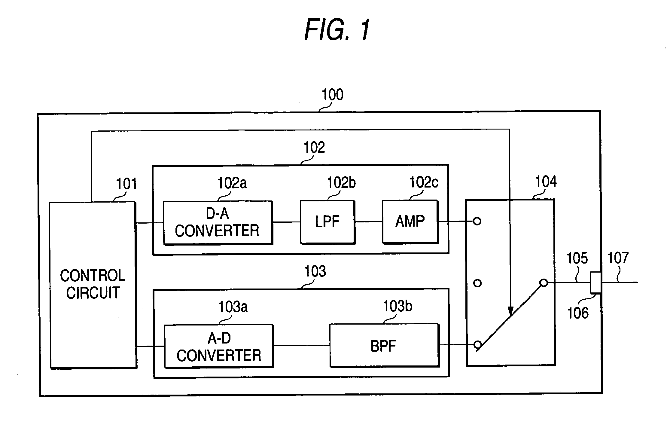
[0026] A transceiver 100 involving at least one of time division multiple communication methods includes a control circuit 101, a transmitting circuit 102, a receiving circuit 103, and a switch 104. The control circuit 101 performs digital signal processing including producing digital transmitting signals and demodulating digital receiving signals, outputs the digital transmitting signals and controls the transmitting circuit 102, the receiving circuit 103, and the switch 104. In this embodiment, FPGA (Field Programmable Gate Alley) is used as the control circuit 101. The control circuit 101 includes a clock. The transmitting circuit 102 converts the digital transmitting signals outputted from the control circuit 101 to analog transmitting signals, and outputs the analog transmitting signals to a transmission line 105 via the switch 104. The transmitting circuit 102 includes a digital / analog converter 102a, a low pass filter 102b and an amplifier 102c. In this embodiment, a D / A conv...

second embodiment

[0034] A channel configuration used in the communication system described in the first embodiment will be described in detail in the second embodiment. TDMA is used as a time division multiple communication method. As shown in FIG. 3, a transmission channel 200 has at least a TDMA channel 200A. Each TDMA channel 200A has a control channel 201 and at least one data channel 202. The transmission channel 200, in general, has a plurality of the TDMA channels 200A as shown in FIG. 3, and the TDMA channel 200A has a data channel 202 including plural data channels 202a, 202b, 202c. The control channel 201 is periodically sent from the transceiver 100 shown in FIG. 1, and shows information about when a communication may start with reference to receiving time of this control channel (Time Information 201a) and which transceivers can communicate with each other (ID Information 201b and 201c). The control channel 201 can include several sets of the time information 201a and the ID information ...

third embodiment

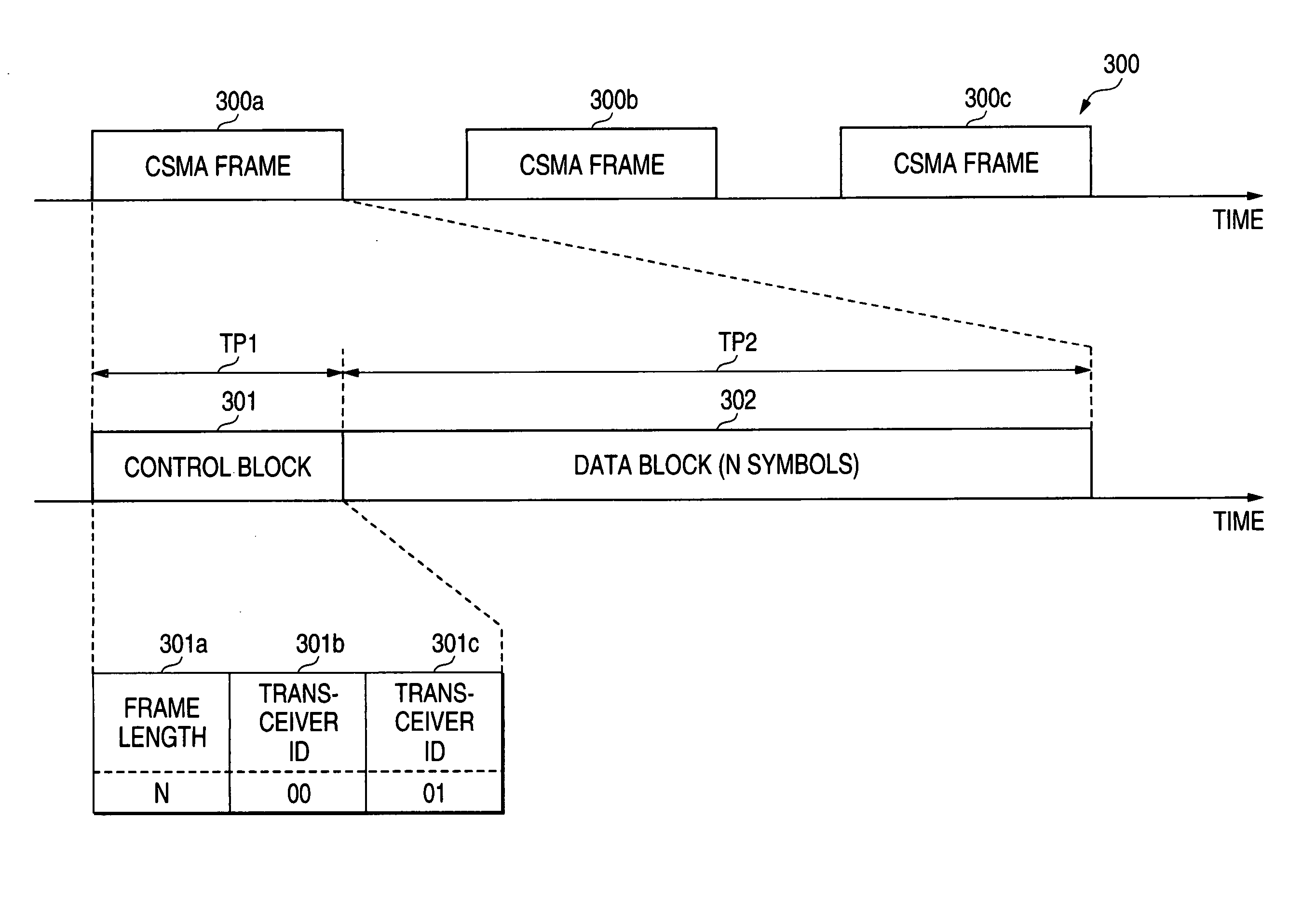
[0044] Another channel configuration used in the communication system described in the first embodiment will be described in detail in the third embodiment. CSMA is used as a time division multiple communication method. As shown in FIG. 6, a CSMA frame 300a includes a control block 301 and a data block 302. The control block 301 includes frame length information 301a, transmitter ID information 301b, and receiver ID information 301c. The control block 301 is a signal section including data that show how long the data will be sent with reference to the time when the control block 301 was received by a transceiver 100. The data block 302 includes N symbols. The data block 302 is a signal section that includes data to be transmitted.

[0045] An operation of a communication system using the above-mentioned frame will be described below.

[0046] Since CSMA is used as a time division multiple transmission method, a transceiver that will receive data has no information about when the CSMA fr...


PUM


Abstract

The present invention relates to a transceiver and communication method involving a time division multiple transmission method, which performs data transmission among a plurality of transceivers. The transceiver includes a transmitter sending data, a receiver receiving data, a switch operable to switch among connecting the transmitter to a transmission line, connecting the receiver to the transmission line, or disconnecting both the transmitter and the receiver to the transmission line or connecting the transmission line to high impedance, and a controller operable to control the switch. The switch connects the transmitter or the receiver to the transmission line at a time that the transceiver has a relation to a communication designated by the time division multiplex transmission method. On the other hand, the switch disconnects the transmitter or the receiver to the transmission line or connects the transmission line to the high impedance at a time that the transceiver does not have a relation to the communication designated by the time division multiplex transmission method.

Description

BACKGROUND OF THE INVENTION [0001] 1. Field of the Invention [0002] The present invention relates to a transceiver and communication method employing time division multiple transmission methods, which performs data transmission among a plurality of transceivers. [0003] 2. Description of the Related Art [0004] Time division multiple transmission methods such as Time Division Multiple Access (TDMA) or Carrier Sense Multiple Access (CSMA) are technologies that multiplex signals of a plurality of channels on the time-axis by sending the signals at different times, respectively. The time division multiple transmission methods are widely used in digital telecommunication and computer networks as described in many books, for example, “OFDM Modulation Technology For Digital Broadcasting And Mobile Communication,” Makoto Itami, Triceps, 2000. [0005] In the time division multiple communication method, transmitted data from a transmitter are divided into base units, which are called “packets”,...

Claims


Application Information

Patent Timeline
Patent Type & Authority Applications(United States)
IPC IPC(8): H04J3/00H04B3/54H04L1/00
CPCH04B3/54H04L1/0003H04B2203/54
Inventor KODAMA, NOBUTAKAKOGA, HISAO
Owner PANASONIC CORP
Why Eureka
Try Eureka