Transmission beam control method, adaptive antenna transmitter/receiver apparatus and radio base station

a technology of transmission beam and receiver, applied in the field of transmission devices, can solve the problems of reducing the subscriber capacity that can be accommodated by limiting the subscriber capacity of the mobile communication system, etc., and achieve the effects of reducing the increase of transmission power, reducing interference power, and increasing the reception power of the mobile station

Inactive Publication Date: 2008-01-29
NEC CORP
View PDF14 Cites 2 Cited by
  • Summary
  • Abstract
  • Description
  • Claims
  • Application Information

AI Technical Summary

Benefits of technology

[0015]When the peak direction of the transmission beam has been changed, the peak direction of the transmission beam can be corrected toward the direction of the mobile station that is the object of transmission. Alternatively, when the width of the main lobe of the transmission beam is increased, the reception power of the mobile station is increased despite slight deviation of the peak direction of the transmission beam from the mobile station that is the object of transmission.
[0016]The consequent reduction of increases in transmission power that are caused when the peak direction of the transmission beam diverges from the mobile station that is the object of transmission enables a reduction of the interference power that is applied to other mobile stations that are present in the peak direction and can prevent a drop in the subscriber capacity of the system.

Problems solved by technology

In a CDMA mobile communication system, a plurality of mobile stations typically use the same frequency band to perform radio communication, and wave interference caused by the radio communication by other mobile stations, i.e., multi-user interference, is a chief cause of limitation of the subscriber capacity of a mobile communication system.
When the peak direction of the transmission beam diverges from the desired wave mobile station, the reception quality of the desired wave mobile station achieves the desired value through the TPC process, but when another mobile station is present in the peak direction of the transmission beam, unnecessary interference power is applied to this mobile station, and the transmission power must therefore be increased to each mobile station.
The maximum transmission power of a radio base station is normally limited by the capability of the power amplifier that supplies power to the antenna devices, and an increase in the transmission power to each mobile station therefore reduces the subscriber capacity that can be accommodated by the mobile communication system.

Method used


Image

  • Transmission beam control method, adaptive antenna transmitter/receiver apparatus and radio base station
  • Transmission beam control method, adaptive antenna transmitter/receiver apparatus and radio base station
  • Transmission beam control method, adaptive antenna transmitter/receiver apparatus and radio base station

Examples


first embodiment

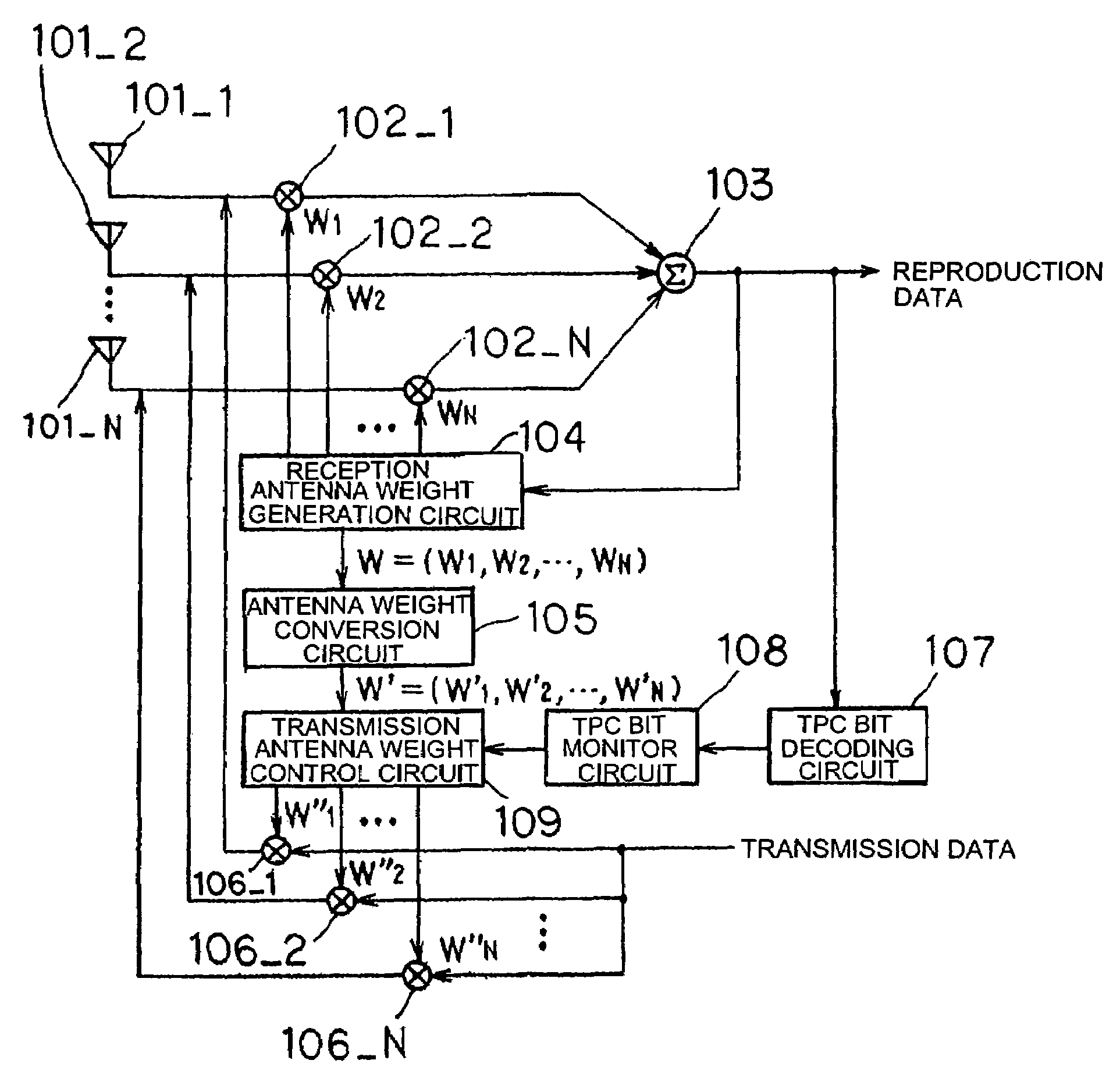
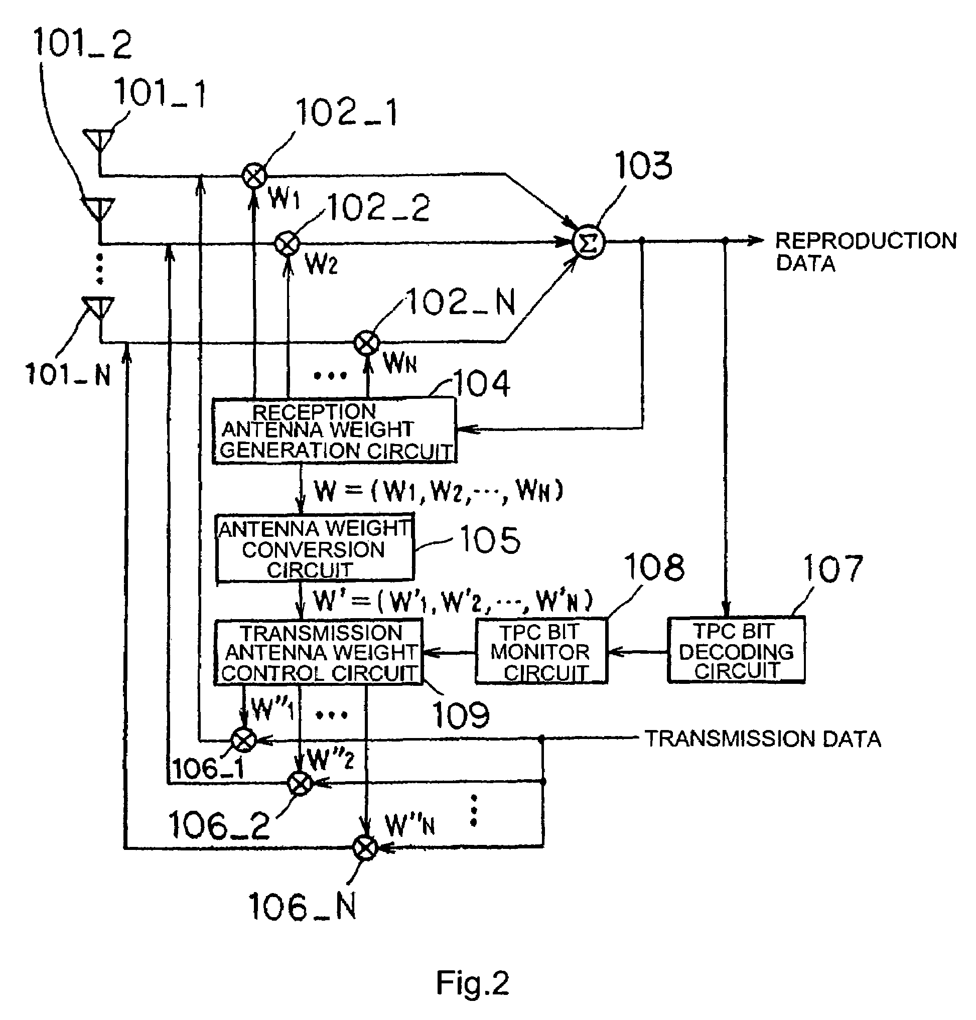
[0029]As shown in FIG. 2, the transceiving device of the first embodiment includes: a plurality (N, where N is a positive integer) of antenna devices 101_1-101_N that are arranged in an array; receiving-side multipliers 102_1-102_N for multiplying reception antenna weights by received signals that have been received by antenna devices 101_1-101_N; adder 103 for adding (synthesizing) the plurality of received signals that have been multiplied by reception antenna weights and supplying the results as reproduction data; reception antenna weight generation circuit 104 for, based on the reproduction data that have been supplied as output from adder 103, calculating optimum reception antenna weights that are to be multiplied with received signals that have been received, and for supplying these optimum reception antenna weights to corresponding receiving-side multipliers 102_1-102_N; TPC bit decoding circuit 107 for extracting TPC bits from reproduction data and decoding instructions for ...

second embodiment

[0049]In the adaptive antenna transceiving device of the second embodiment, the transmission beam control procedure by transmission antenna weight control circuit 109 differs from that of the first embodiment. The configuration and operations are otherwise the same as the first embodiment, and redundant explanation is therefore omitted.

[0050]As shown in FIG. 6, in the adaptive antenna transceiving device of the second embodiment, a process is executed by transmission antenna weight control circuit 109 for alternately moving the peak direction of transmission beam 3 toward the left and right when the results of decoding the TPC bits in a prescribed interval show a bias toward instructions for increasing the transmission power. In the present embodiment, the peak direction is moved toward the right (or toward the left) by angle L that has been set in advance (“a” of FIG. 6) with respect to transmission beam 3 that is formed by first transmission antenna weights W′=(w′1, w′2, . . . , w...

third embodiment

[0057]In the adaptive antenna transceiving device of the third embodiment, the control procedure of the transmission beam by means of the transmission antenna weight control circuit differs from that of the first embodiment and the second embodiment. The configuration and operations are otherwise identical to the first embodiment, and redundant explanation is therefore omitted.

[0058]In the adaptive antenna transceiving device of the third embodiment, when the results of decoding the TPC bits are biased toward instructions for increasing the transmission power, the width of the main lobe is increased by a preset angle of ±H (where “+” is toward the right and “−” is toward the left) with respect to the transmission beam that is formed by the first transmission antenna weights W′=(w′1, w′2, . . . , w′N). If the conditions do not then improve (if the results of decoding the TPC bits are still biased toward instructions for increasing transmission power), the width of the main lobe of th...


PUM


Abstract

Changes in instructions for increasing / decreasing transmission power that have been decoded from TPC bits are monitored, and when the increase / decrease instructions in a prescribed time interval are biased toward instructions for increasing the transmission power, the peak direction or main lobe width of the transmission beam is changed by regulating the transmission power or transmission antenna weights that correspond to each of a plurality of antenna devices. These processes are repeated until the bias toward instructions for increasing the transmission power in the instructions for increasing / decreasing transmission power is eliminated or until the number of changes of the transmission beam reaches a maximum value that has been set in advance.

Description

TECHNICAL FIELD[0001]The present invention relates to transceiving device that is suitable for use in a Code Division Multiple Access (hereinbelow abbreviated as CDMA) mobile communication system.BACKGROUND ART[0002]In a CDMA mobile communication system, a plurality of mobile stations typically use the same frequency band to perform radio communication, and wave interference caused by the radio communication by other mobile stations, i.e., multi-user interference, is a chief cause of limitation of the subscriber capacity of a mobile communication system. To increase the subscriber capacity, the adaptive antenna technology is effective for suppressing interference waves during reception, and during transmission, for avoiding transmission in unnecessary directions and thus reducing interference power that is applied to other mobile stations.[0003]As a prior-art example of a transceiving device that adopts the adaptive antenna technology (hereinbelow referred to as an adaptive antenna ...

Claims


Application Information

Patent Timeline
Patent Type & Authority Patents(United States)
IPC IPC(8): H04B1/00H04B1/707H04B7/005H04J13/00
CPCH04W52/42Y02B60/50H04B7/0617H04B7/0634H04B7/15528H04B7/2606Y02D30/70
Inventor MIZUGUCHI, HIRONORI
Owner NEC CORP
Why Eureka
Try Eureka