

Method and apparatus for video image interpolation with edge sharpening
- Summary
- Abstract
- Description
- Claims
- Application Information
AI Technical Summary
Benefits of technology
Problems solved by technology
Method used
Image

Examples
Embodiment Construction
[0015] In one embodiment the present invention provides a method and apparatus for video sample interpolation with edge sharpening, whereby edge sharpness can be essentially preserved and / or enhanced in the interpolated image.
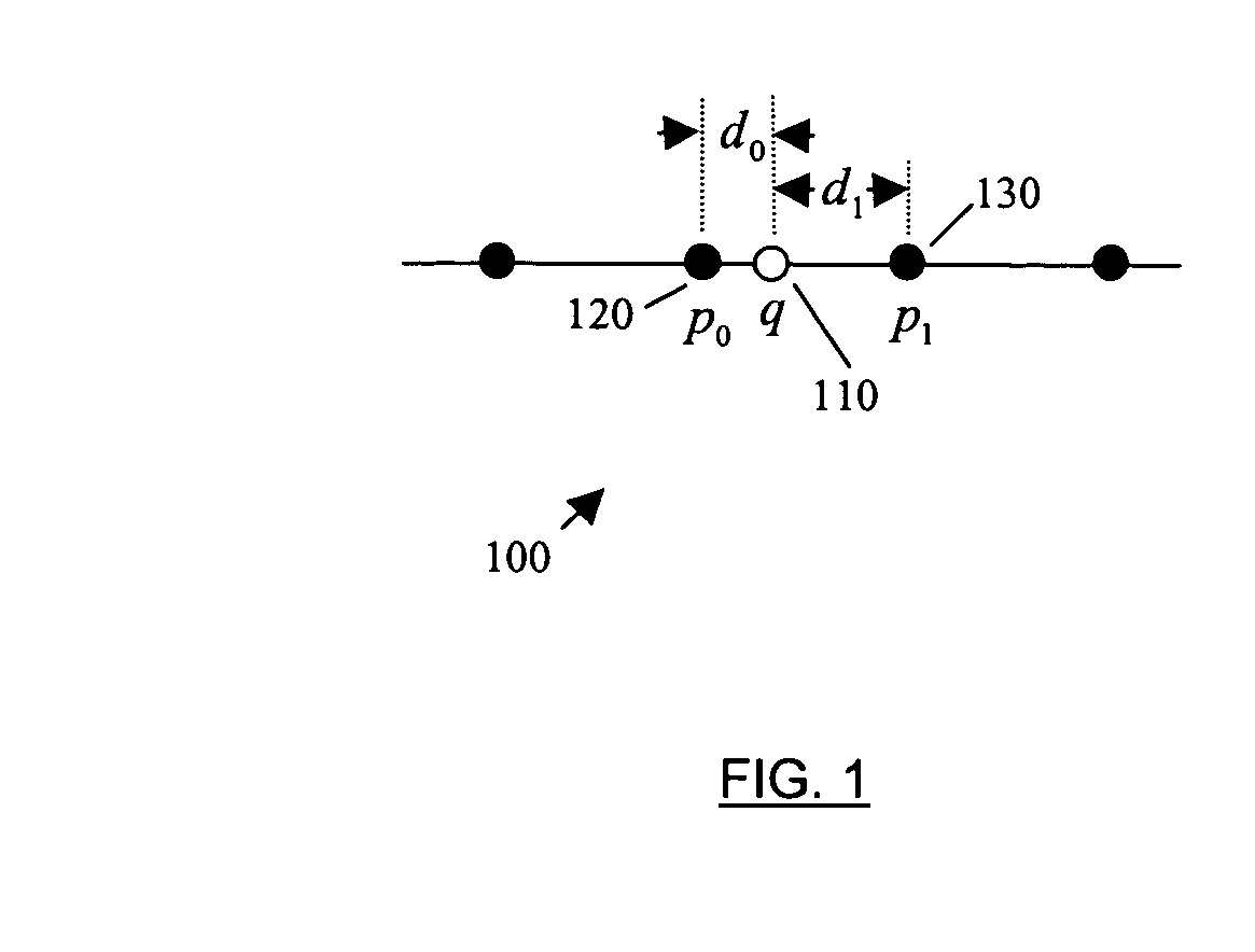
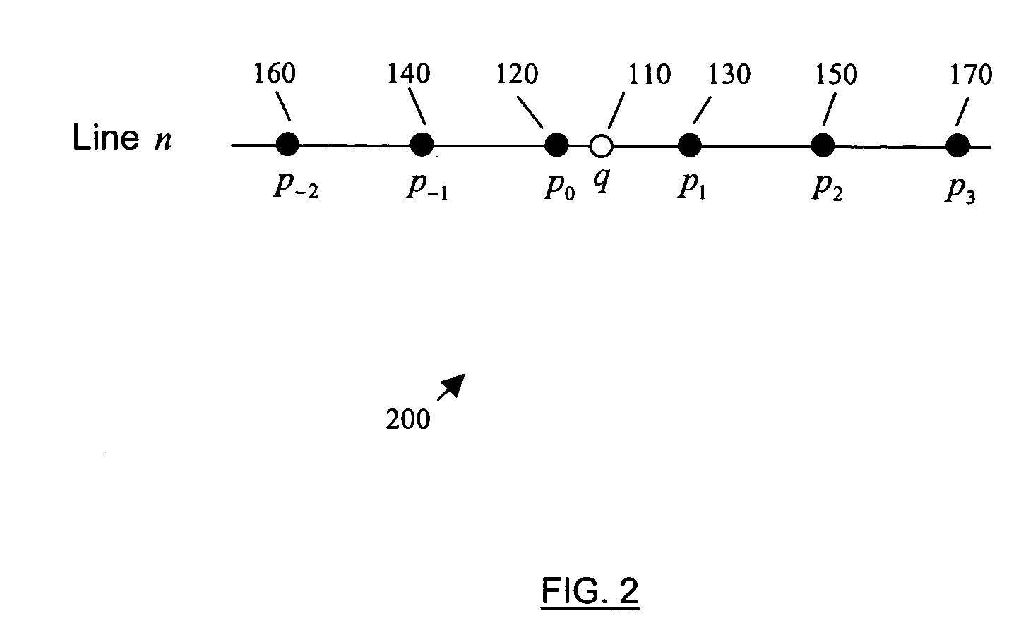
[0016] In a conventional interpolation process, a new sample is generated based on the values of original image samples that are neighboring to the new sample position as well as the relative locations of those original image samples to the new sample. FIG. 1 shows an example set of pixels 100 in which a new sample is interpolated based on its two closest neighboring original pixels. In FIG. 1, a hollow circle 110 represents the position where the new sample q is to be interpolated. The solid circles 120, 130 represent original pixel positions p0 and p1 as two closest neighboring original pixels of q. In the following description, p0, p1 and q, etc. are used to refer both the sample location and the sample value. The distances to q from pixels p0 and p1 are ex...
PUM
 Abstract
Description
Claims
Application Information