
Iterative approach for applying multiple currents to a body using voltage sources in electrical impedance tomography

a technology of electrical impedance tomography and multiple currents, applied in the field ofeit, can solve the problems of small changes in currents or voltages at the surface, difficult and expensive construction of current sources, and reconstruction problems

Inactive Publication Date: 2005-11-10
RENSSELAER POLYTECHNIC INSTITTUTE
View PDF4 Cites 34 Cited by
  • Summary
  • Abstract
  • Description
  • Claims
  • Application Information

AI Technical Summary

Benefits of technology

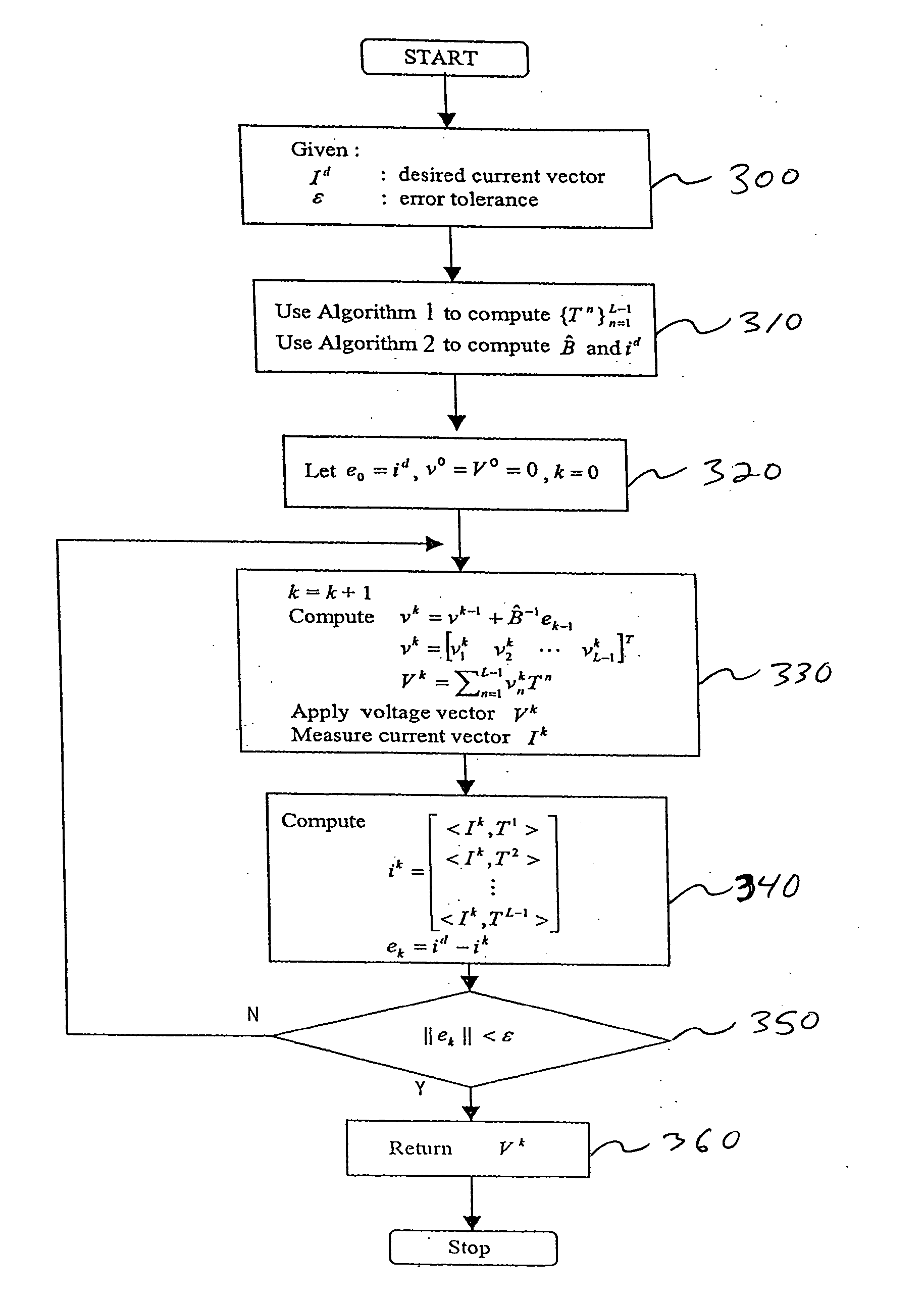
[0016] A third algorithm includes computing and applying to the electrodes, the voltages of the voltage vector as a function of the estimate of the non-singular linear mapping matrix and the coordinate vector for the desired current vector. The resulting current vector is measured. The coordinate vector is computed for the measured resulting current vector with respect to the orthonormal basis set. The last part of this third algorithm involves calculating a norm of the actual error between the coordinate vector for the measured resulting current vector and the coordinate vector for the desired current vector. If the norm of the actual error is less than the selected error tolerance, the computed voltage vector of the third algorithm is used in a plurality of voltage sources to create voltage patterns, which are applied to the electrodes of an EIT system to create resulting current patterns in the body. The resulting current patterns are measured at the electrodes to determine the conductivity and permittivity distributions within the body.

Problems solved by technology

The image reconstruction problem in EIT is ill-posed, and large changes in the conductivity and permittivity in the interior can produce small changes in the currents or voltages at the surface.
In practice, however, current sources are difficult as well as expensive to build.
Building a high precision current source is a technologically challenging task.
It is even more difficult to design a current source if the EIT system is to operate over a wide range of signal frequencies, as is required for EIT spectroscopy.
The implementation of high-precision current sources has generally required the use of calibration and trimming circuits to adjust output impedance up to sufficient levels, yielding relatively complex circuits.
EIT systems using voltage sources have been implemented, though these systems suffer from increased sensitivity to the high frequency noise described above.

Method used


Image

  • Iterative approach for applying multiple currents to a body using voltage sources in electrical impedance tomography
  • Iterative approach for applying multiple currents to a body using voltage sources in electrical impedance tomography
  • Iterative approach for applying multiple currents to a body using voltage sources in electrical impedance tomography

Examples


Embodiment Construction

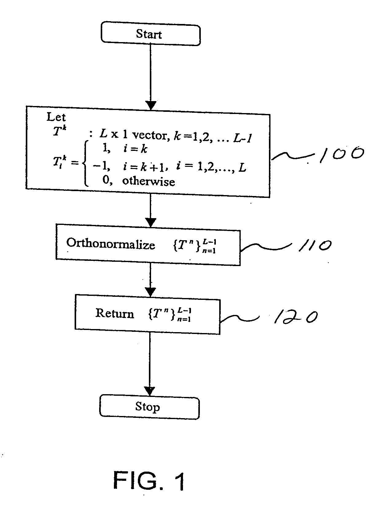
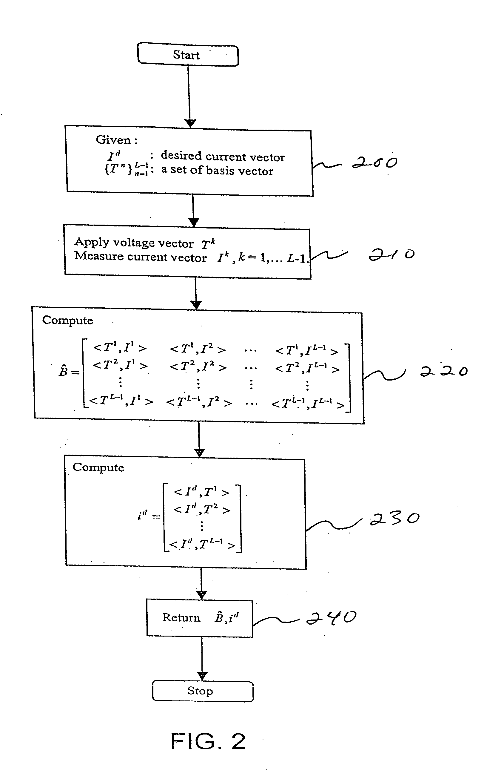
[0027] For the purpose of explaining the present invention, let I=(I1, I2, . . . Il)T denote an L×1 electrode current vector where In is the current value on electrode n, and L is the number of electrodes. Similarly, let V=(V1, V2, . . . Vl)T denote an L×1 electrode voltage vector. The mapping from the applied electrode voltage V to the measured electrode current I can be represented using a constant L×L matrix A, so that I=AV, provided that the change with time in the electrical conductivity of human body under examination is assumed to be negligible or the change is slow compared to the fast sampling time of the measurement data. Since the magnitude and the phase of the currents and voltages are used in the conductivity and permittivity reconstruction, the elements of I, V and A are complex numbers.

[0028] The goal is to compute voltage Vd that will generate the desired electrode current pattern Id. The exact value of A can not be determined. The estimate of A, denoted as Â, can b...


PUM


Abstract

Voltage sources produce desired current patterns in an ACT-type Electrical Impedance Tomography (EIT) system. An iterative adaptive algorithm generates the necessary voltage pattern that will result in the desired current pattern. The convergence of the algorithm is shown under the condition that the estimation error of the linear mapping from voltage to current is small. The simulation results are presented along with the implication of the convergence condition.

Description

CROSS-REFERENCE TO RELATED APPLICATION [0001] This U.S. patent application claims priority on, and all benefits available from U.S. provisional patent application No. 60 / 569,549 filed May 10, 2004, all of which is incorporated here by reference.STATEMENT OF GOVERNMENT INTEREST [0002] Development of the present invention was supported, in part, by CenSSIS, the Center for Subsurface Sensing and Imaging Systems, under the Engineering Research Center Program of the National Science Foundation (Award number EEC-9986821).FIELD AND BACKGROUND OF THE INVENTION [0003] The present invention relates generally to the field of EIT, and in particular to a new and useful appartaus and method for Adaptive Current Tomography (ACT). [0004] Electrical Impedance Tomography (EIT) is a technique for determining the electrical conductivity and permittivity distribution within the interior of a body from measurements made on its surface. Typically, currents are applied through electrodes placed on the body...

Claims


Application Information

Patent Timeline
Patent Type & Authority Applications(United States)
IPC IPC(8): A61B5/05A61B5/053
CPCA61B5/0536
Inventor CHOI, MYOUNGISAACSON, DAVIDNEWELL, JONATHAN C.
Owner RENSSELAER POLYTECHNIC INSTITTUTE
Learn More