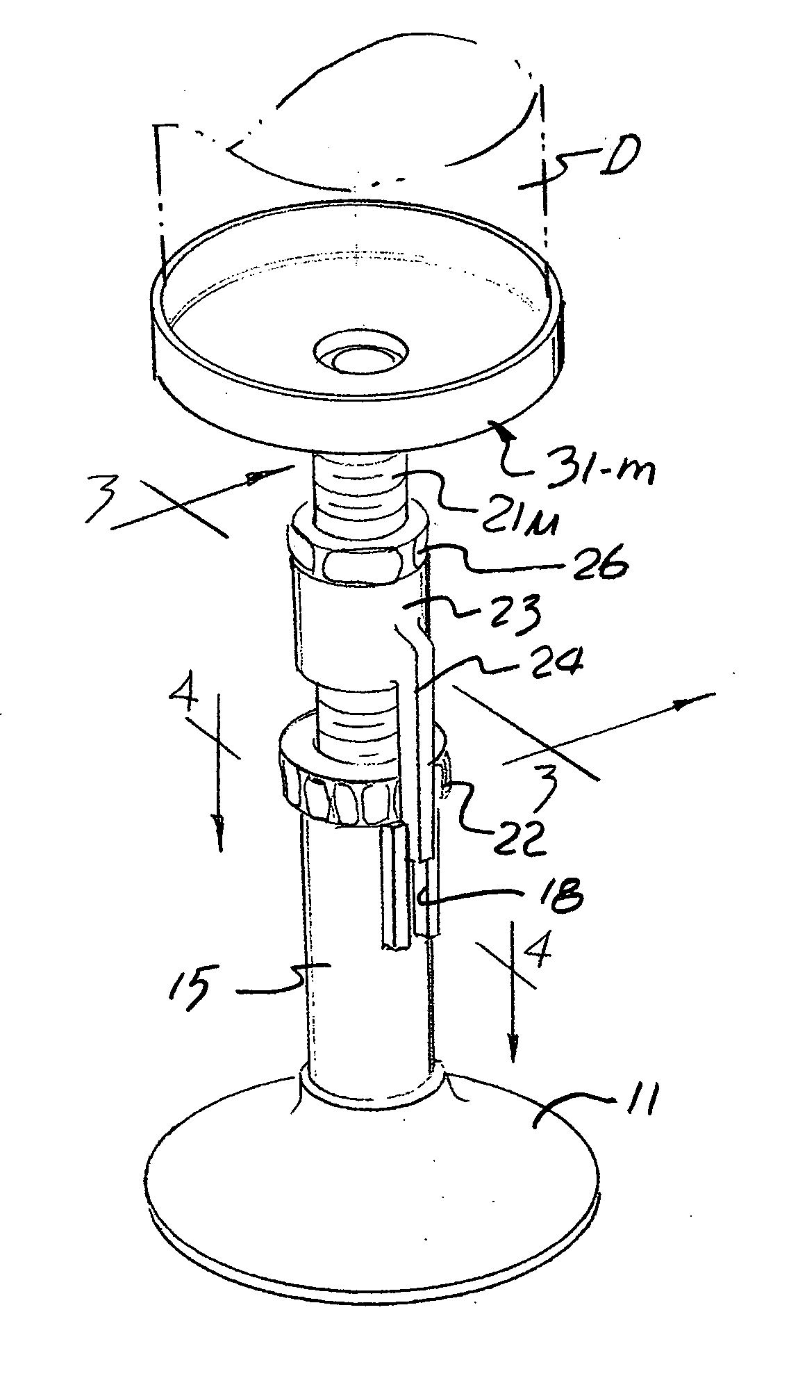
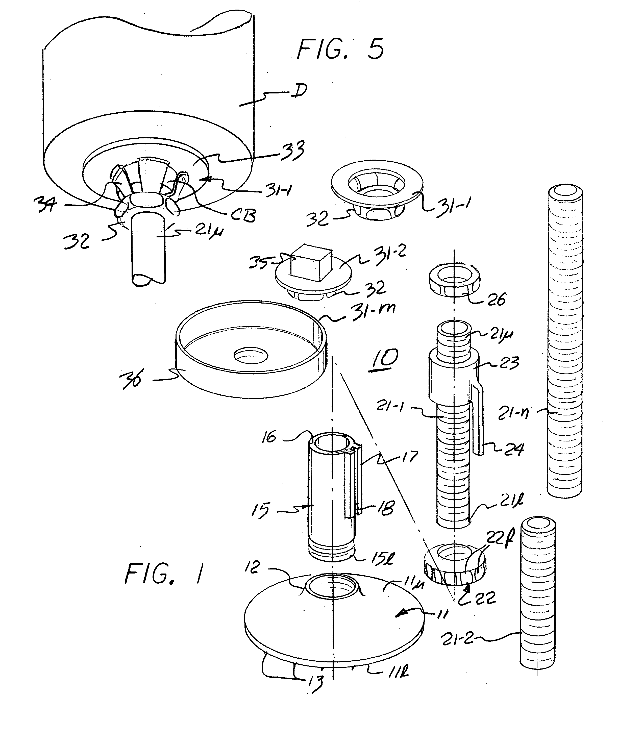
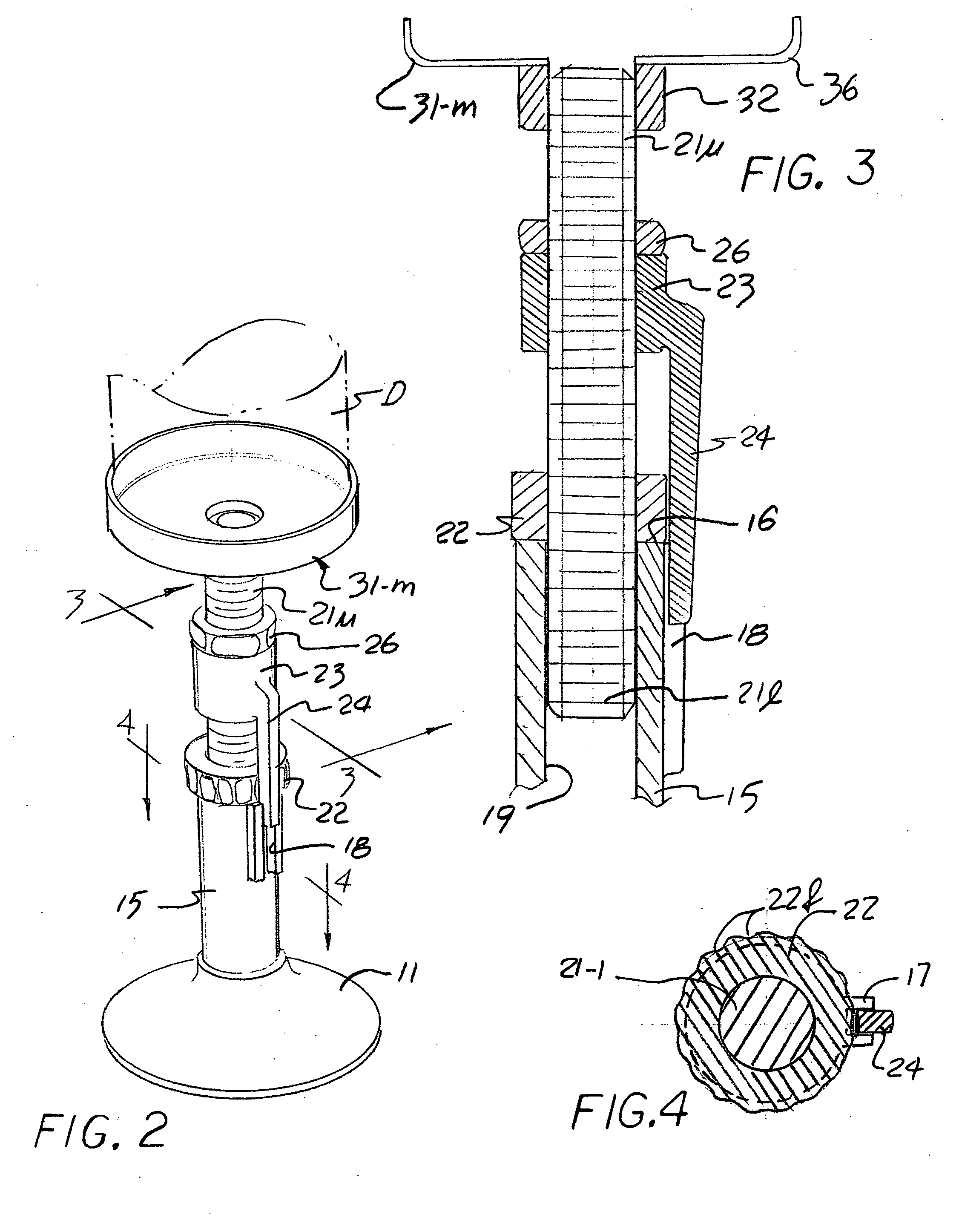
[0018] As shown in FIGS. 1-4, the inventive support assembly, generally designated by the numeral 10, comprises a base 11 of a generally planar configuration provided with a threaded boss 12 on the upper surface 11u thereof. The peripheral edge surface of the lower surface 11l may be finished to a rough finish, shown by projections 13, to increase frictional resistance to any rotary displacement thereof A pipe segment 15 exteriorly threaded over the lower end surface 15l is then threadably insertable into the boss 12 to form a vertically aligned annular structure supported on the base and defined at the upper end 15u by a smoothed end surface 16. A longitudinally aligned channel piece 17 is then affixed to the outer surface of segment 15 to present a radially directed recess 18 extending from surface 16 along a portion of segment 15.
[0019] A selected one of a plurality of threaded rods 21-l through 21-n, shown as rod 21 -l in the Figure, is then threadably received in the interior of a nut assembly 22 to extend a lower portion 21l into the interior bore 19 of segment 15. This extension is limited by the resting abuttment of the assembly 22 against the smoothed surface 16 and is adjustable by the rotary advancement of the assembly on rod 21-l. In this manner the extension of the upper rod portion 21u is manually selectable by rotary manipulation of the nut assembly. To allow for such one-handed manipulation of the nut assembly 22 on rod 21-l a threaded sleeve 23 is advanced onto the upper rod segment 21u to deploy an offset bar 24 aligned for receipt within recess 18, thus fixing the rod in rotation. To further secure sleeve 23 on the rod a clamping nut 26 may be provided, or alternatively the sleeve may be compressed against any support adaptors that may be threaded onto the rod end. Of course, these alternatives depend on the length of the rod selected and the desired height of the adapter deployment, a dimension determined by the size of the article supported on the adapter and the height to which it needs to be raised.
[0020] Those skilled in the art will appreciate that commercially available disposals D are variously implemented and the geometry of their lower surfaces will therefore need various conforming support structures. For this reason a plurality of adapters 31-l through 31-m is provided as a part of the assembly array each conformed to a particular disposal geometry and each characterized by a central mounting nut 32 conformed for mounting on the corresponding upper rod end 21u. For example, for those configurations of the disposal D provided with an annular central boss CB (see FIG. 5) the structure of adapter 31-1 provides an annular ring 33 mounted on nut 32 by a spider 34. Alternatively, disposals D provided with a key opening in their lower surface for clearing jams may take advantage of the adapter 31-2 provided with an upward key 35 and configurations that include a flat lower surface may use the dished support 36 shown on adaptor 31-m (and illustrated in FIGS. 2 and 3). Of course, other disposal shapes can be similarly accommodated.
[0021] In each instance it is the deployment convenience of a support structure that is easily adjusted that is desired, particularly when raising the disposal into compressive contact with the seals and brackets that form the mounting structure. To preclude inadvertent reduction in height a retention interlock is conveniently formed by providing a series of flats or depressions 22d on the periphery of the nut assembly 22 on which the offset bar 24 rests as it is cantilevered from sleeve 23. The manual advancement of the nut assembly is therefore against a spring bias, assuring positive engagement at the position selected. In this manner a conveniently assembled tool is provided that is easily configured for various installation geometries. Moreover, the generally conventional nature of most of the components of the assembly assures a broad selection of materials such as metal, PVC or other polymeric structures.
[0022] Of particular interest to those engaged in the installation or re-installation of disposals and macerators is the range of utility of this support assembly which can be further expanded by combining the several pieces in any selection. For example the very short rod 21-2 may be combined with one of the other, longer, ones by threaded insertion into both the ends of sleeve 23 and the annular support 31-1 may be combined with adapter 31-2 for those instances where both a key opening and a central boss is included in the disposal end. Thus a wide range of shapes and dimensions is conveniently accommodated.
[0023] Obviously, many modifications and variations can be effected without departing from the spirit of the invention instantly disclosed. It is therefore intended that the scope of the invention be determined solely by the claims appended hereto.