Welding wire positioning system

a positioning system and welding wire technology, applied in the direction of soldering equipment, manufacturing tools, instruments, etc., can solve the problems of welding wire wobble, inferior weld, weld wiggle of the weld bead on the workpiece, etc., to minimize the effect of conduit re-casting and minimize the movement of wires

Inactive Publication Date: 2005-11-17
LINCOLN GLOBAL INC
View PDF35 Cites 91 Cited by
  • Summary
  • Abstract
  • Description
  • Claims
  • Application Information

AI Technical Summary

Benefits of technology

[0011] In another and / or alternative aspect of the present invention, the electromagnetic wave generator includes or is a scanning laser that emits a line of laser beam and / or a structured light pattern projector. In one embodiment of the invention, the line of laser beam and / or strip of light has a width of about 2-100 mm, typically about 5-50 mm, and more typically about 10-40 mm. Generally the line of the laser beam and / or strip of light has a width which is greater than the diameter of the welding wire, and typically at least about 1½ times the diameter of the welding wire, more typically at least about 2 times the diameter of the welding wire and still more typically at least about 2.5 times the diameter of the welding wire. The selected width of the line of laser beam and / or strip of light is typically great enough such that the welding wire substantially maintains its position within the width of the laser beam line and / or strip of light during the welding process so that the complete wire wobble movement of the welding wire can be ascertained during the welding process. In still another and / or alternative embodiment of the invention, the electromagnetic wave generated by the electromagnetic wave generator is at least partially directed laterally across the welding wire during a welding process. Generally, the electromagnetic wave substantially lies in a lateral plane that is directed at least partially across the welding wire in a welding process. The angle of orientation of the lateral plane of the electromagnetic wave relative to the longitudinal axis of the welding wire and / or the contact tip of the welding gun is generally about 20-90°, typically about 40-90°, and more typically about 45-90°. In one aspect of this embodiment, the lateral plane of the electromagnetic wave is substantially perpendicular (i.e., 90°) to the longitudinal axis of the welding wire and / or the contact tip of the welding gun. The electromagnetic wave is generally directed at the welding wire at a location below the end of the contact tip of the welding wire. Generally, the electromagnetic wave is projected laterally across the welding wire at a location which is at least about 0.01 inch below the end of the contact tip of the welding gun, typically about 0.05 to 2 inches below the end of the contact tip of the welding gun, more typically about 0.1 to 1.8 inches below the contact tip of a welding gun, even more typically about 0.2 to 1.75 inches below the contact tip of the welding gun, and still even more typically about 0.25 to 1.5 inches below the contact tip of the welding gun. The directing of the electromagnetic wave laterally across the welding wire in a position below the end of the contact tip better enables the detection mechanism to monitor the wire wobble of the welding wire as it exits the contact tip of the weld gun.
[0025] Another and / or alternative object of the present invention is the provision of a placement mechanism and method which correlates sensitivity of conduit routing geometry to be used to design wire shape memory and winding techniques that minimize the effect of conduit re-cast.

Problems solved by technology

For such a robotic welder to operate efficiency, both the welding equipment and the workpiece must be precisely positioned with reliable repetition since any deviation in the welding equipment and / or position of the workpiece or the path of the joint to be welded will be result in an inferior weld.
Although many of these positioning systems for robotic welders have provided satisfactory orientation of the welding gun relative to the welding location, these positioning systems do not account for welding wire wobble during a welding process.
Such movement of the weld wire results in weld wiggle of the weld bead on a workpiece.
However, none of these positioning systems have so addressed or successfully addressed wire wobble problems.
The wire wobble problem can be significant during the welding process and can be as great as an order of magnitude of the welding wire diameter.
In the past, wire straighteners have been used in attempt to alleviate the problem of wire wobble; however, use of wire straighteners have not proven successful in dealing with such problems due to delicate setup and lack of standardization on a factory floor.
This method is not proven effective to test large quantities of wire with good repeatability, and furthermore can be very expensive and time consuming.
Although this method of detecting weld wobble has had some success, the video camera has a low frame rate and is adversely affected by lighting thus reducing the effectivity of detection.
Laser sensors have also been used to measure wire movement under the contact tip, however, such past systems have been inhibited by the formation of a weld bead on a metal plate and the cost for such arrangements.
Other methods of detecting wire wobble have also met with low success such as the use of a plasma arc to deflect the wire by arc force, or the use of induction heating of the weld wire which can be cost prohibitive.

Method used


Image

  • Welding wire positioning system
  • Welding wire positioning system
  • Welding wire positioning system

Examples


Embodiment Construction

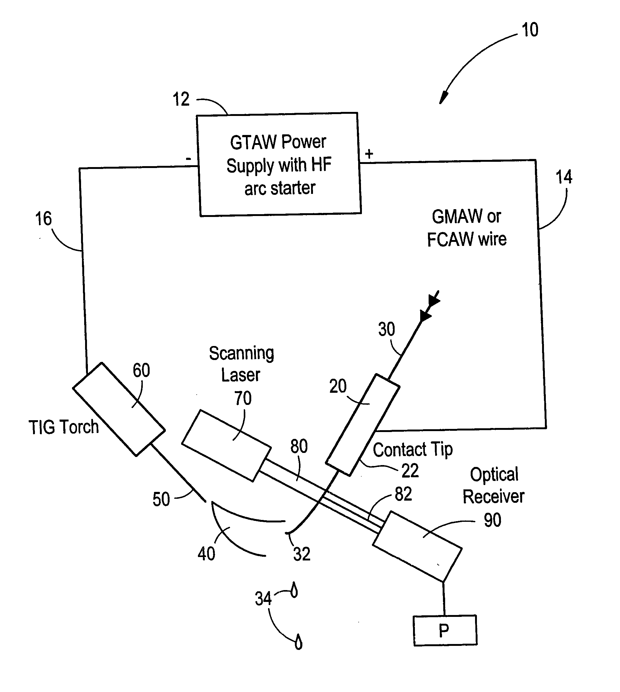
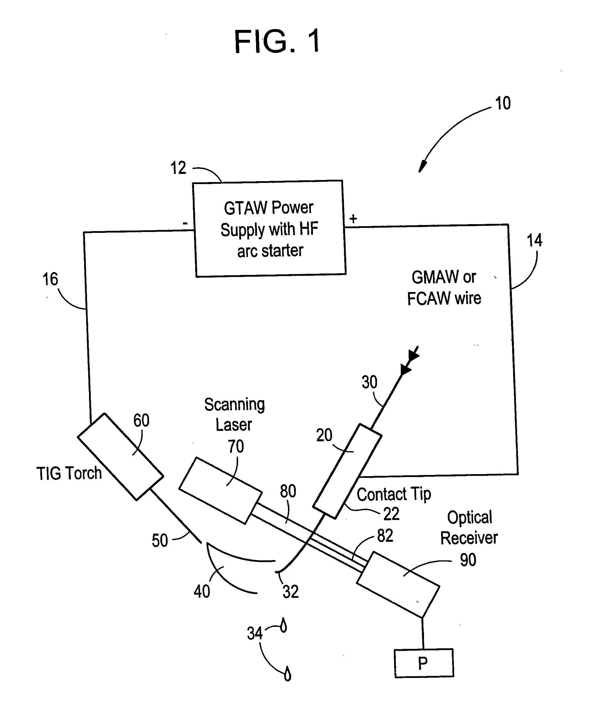
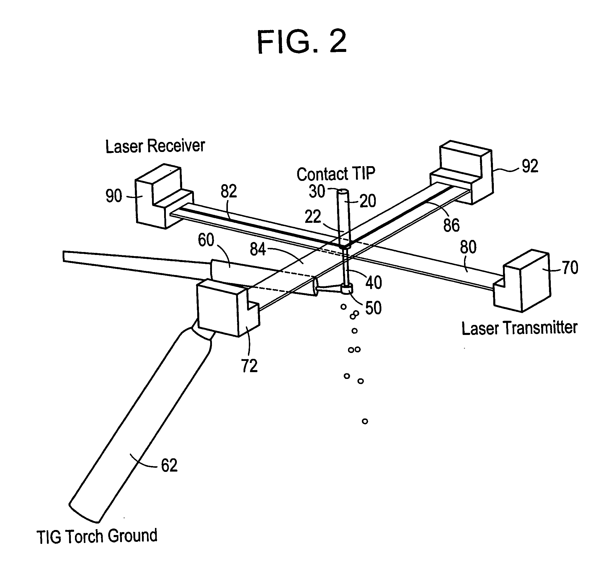
[0036] Referring now to the drawings wherein the showings are for the purpose of illustrating a preferred embodiment of the invention only and not for the purpose of limiting same, FIG. 1 illustrates a basic arc welding arrangement. The arc welding arrangement includes a gas TIG arc welding (GTAW) power supply with a high frequency (HF) arc starter 12. The operation of a gas TIG arc welder power supply is well known in the art thus no further discussion will be made with respect to such power supply. Examples of power supplies that can be used include, but are not limited to, U.S. Pat. Nos. 5,683,602; 5,338,916; 5,285,042; 4,947,021; and 4,385,223; all of which are incorporated herein by reference. One pole of the GTAW power supply is connected to a contact tip 20 of an arc welding gun by electrical connection 14. A welding wire 30 is illustrated as being fed through the contact tip of the welding gun. The design of the contact tip and the use of a contact tip in a welding gun are w...


PUM

PropertyMeasurementUnit
wavelengthaaaaaaaaaa

Abstract

An electrode position detection system for a welder having a laser that is projected in a lateral plane to laterally cross a welding wire at a location below a contact tip of a welding gun and a receiver that receive the laser bean after crossing the welding wire, and a measuring device that determines one or more parameter of the welding wire based on the received laser beam. Arc voltage measurements can also be used to determine one or more parameter of the welding wire.

Description

[0001] This invention relates generally to arc welding and more particularly to a consumable electrode position detection system and method thereof for arc welders. BACKGROUND OF INVENTION [0002] Arc welding systems are currently used with robotic welding systems. The use of such robotic welding systems is typically to improve welding uniformity and reproducibility, and to increase the productivity and reduce the cost of welding. It is common that the robotic welder is responsible for carrying out, handling and / or manipulating the welding gun during a welding process. Some robotic systems have been developed which are preprogrammed to perform a fix sequence of motion and process actions. In such a system, the robotic welder merely repeats sequence of motions and processes for each weld. For such a robotic welder to operate efficiency, both the welding equipment and the workpiece must be precisely positioned with reliable repetition since any deviation in the welding equipment and / or...

Claims


Application Information

Patent Timeline
Patent Type & Authority Applications(United States)
IPC IPC(8): B25J19/02B23K9/095B23K9/12B23K9/127B23K9/133B23K9/167
CPCB23K9/0953B23K9/0956B23K9/1675B23K9/126B23K9/124B65G47/24B65G2203/0225B65G2203/044G01B11/26
Inventor HSU, CHRISTOPHERSTAVA, ELLIOTT K.KLEIN, JEFFREY R.BARTON, DAVID J.BLANKENSHIP, GEORGE D.
Owner LINCOLN GLOBAL INC
Why Eureka
Try Eureka