
Gamma ray detector for positron emission tomography (pet) and single photon emisson computed tomography (spect)

Inactive Publication Date: 2005-11-17
EUROPEAN ORGANIZATION FOR NUCLEAR RESEARCH
View PDF8 Cites 83 Cited by
  • Summary
  • Abstract
  • Description
  • Claims
  • Application Information

AI Technical Summary

Benefits of technology

[0009] It is an object of the present invention to provide an improved gamma ray detector, particularly for Positron Emission Tomography (PET) and Single Photo Emission Computed Tomography (SPECT), with improved sensitivit

Problems solved by technology

The radial coordinate, i.e. the depth of interaction, is however not determined, leading to a degraded reconstruction precision due to parallax errors.
Nevertheless the resolution achievable for the radial coordinate is still poor.
However, a

Method used


Image

  • Gamma ray detector for positron emission tomography (pet) and single photon emisson computed tomography (spect)
  • Gamma ray detector for positron emission tomography (pet) and single photon emisson computed tomography (spect)
  • Gamma ray detector for positron emission tomography (pet) and single photon emisson computed tomography (spect)

Examples


Example

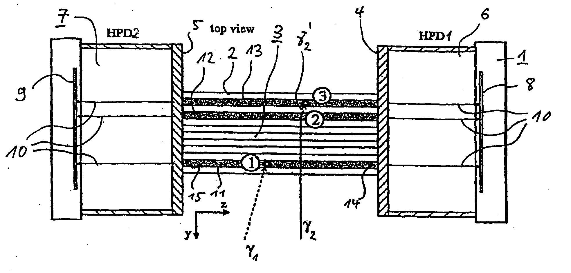
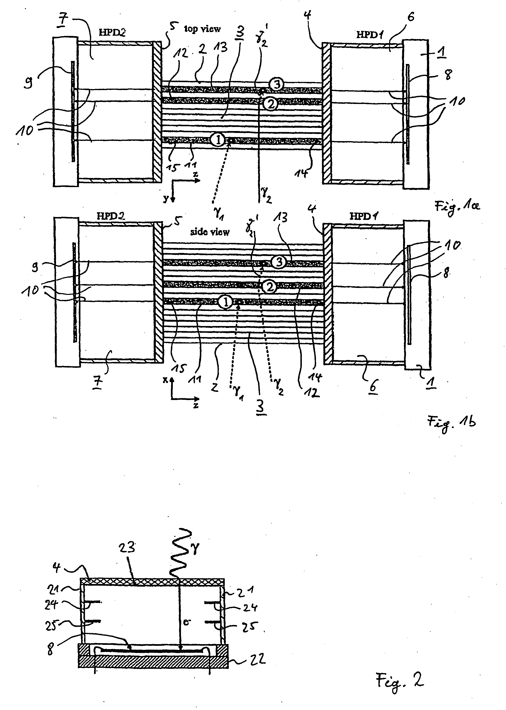
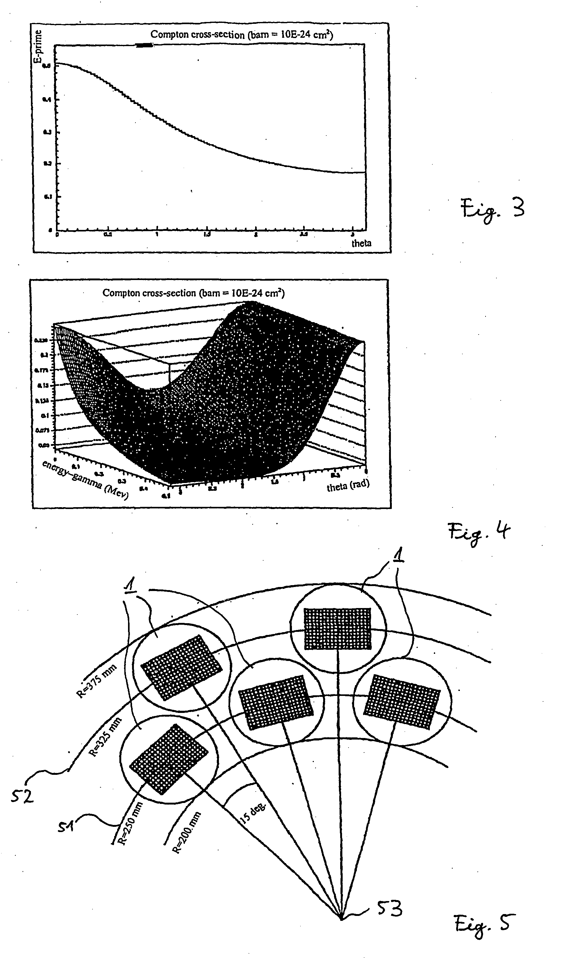
[0028]FIG. 1a displays a top view of a schematic drawing of a detector module 1 according to the invention. Said detector module 1 comprises scintillator crystals 2 arranged in a regular matrix 3. The scintillator crystals 2 are of longitudinal shape. The preferred dimensions of each of said scintillator crystals 2 are: 3.2×3.2×100 mm3. Said scintillator crystals 2 of 100 mm length can be made by joining two or three shorter scintillator crystal segments with a glue of an appropriate refractive index. All surfaces of said scintillator crystals 2 are polished. The scintillator crystals 2 are equally spaced in said regular matrix 3. A preferred gap between each of said scintillator crystals 2 is 0.8 mm. Said gaps between said crystals 2 allow the insertion of blinds, for example, black paper, to prevent light being transferred from one of said crystals 2 to another of said crystals 2. Said scintillator crystals 2 are oriented parallel to each other and such, that midpoint of said scin...


PUM


Abstract

The invention relates to a detector module (1) for a Positron Emission Tomograph (PET) and for Single Photon Emission Computed Tomography (SPECT) comprising a matrix (3) of scintillator crystals, said matrix having a first side and a second side opposite to said first side, each scintillator crystal having a first end (14) and a second end (15), said scintillator crystals (2) being oriented parallel to each other, whereby said first end (14) and said second end (15) of each of said scintillator crystals (2) coincide with said first side and said second side of said matrix (3), respectively; a first light sensitive detector (6) producing electrical signal proportional to the amount of light detected, being optically connected to said first side of said matrix (3), said first light sensitive detector (6) being position sensitive; and a second light sensitive detector (7) producing electrical signal proportional to the amount of light detected, said second light sensitive detector (7) being optically connected to said second side of said matrix (3), wherein said second light sensitive detector (7) is positioned sensitive. Using said detector module (1) a method to determine the 3D-coordinates of a point of interaction of a gamma quantum (γ1, γ2) with said detector module (1) is disclosed method. This allows to use signals from compton seattered γ's to enhance the sensitivity of a Positron Emission Tomograph scanner provided being composed of said detection modules (1) without parallax errors.

Description

[0001] The invention relates to position and energy sensitive gamma ray detectors and a method to determine the points of interaction of gamma rays with such gamma ray detectors, particularly to gamma ray detectors for Positron Emission Tomography (PET) and Single Photo Emission Computed Tomography (SPECT). BACKGROUND OF THE INVENTION [0002] In recent years Positron Emission Tomographs (PET) have become an increasingly important diagnostic tool in medicine as well as in biology. [0003] Positron Emission Tomographs provide quantitative measurements on the metabolism of internal organs and their biochemistry by in vivo measuring specific activities of positron emitting radio-nuclides. The most commonly used radio-nuclide is the isotope 18F in fluorodeoxyglucose (FDG). Over the last 20 years a continuous development of PET scanners have demonstrated a tremendous potential for cancer diagnosis and treatment. [0004] Conventional PET systems in use for medical application employ gamma det...

Claims


Application Information

Patent Timeline
IPC IPC(8): G01T1/20G01T1/161G01T1/29H01L31/09
CPCG01T1/2985
Inventor JORAM, CHRISTIANSEGUINOT, JAQUESWEILHAMMER, PETER
Owner EUROPEAN ORGANIZATION FOR NUCLEAR RESEARCH
Learn More