Preloaded suspension bracket assembly for axle housing

a technology for suspension brackets and axle housings, which is applied in the direction of springs/dampers, mechanical equipment, transportation and packaging, etc., can solve the problems of increasing cost, proliferating components, and creating many design challenges at the mount interface, and achieves the effect of easy incorporation

Inactive Publication Date: 2005-11-17
ARVINMERITOR TECH
View PDF5 Cites 47 Cited by
  • Summary
  • Abstract
  • Description
  • Claims
  • Application Information

AI Technical Summary

Benefits of technology

[0007] In one disclosed embodiment, the suspension bracket assembly includes a first bracket member and a second bracket member. The bracket members are held fixed relative to each other and then are slid over one end of the axle housing to substantially surround the axle housing. The bracket members can be held fixed relative to each other by being clamped together in a fixture, hinged together, or fastened together prior to being installed over the axle housing. Once in position, the first and second bracket members are attached to each other. This attachment can be a welded or bolted joint. During attachment, the preload force is applied to the first and second bracket members, which exert the clamping or preload force against the housing to control the suspension load path.
[0008] The first and second bracket members are geometrically configured to ensure positive contact for the clamping force only along predetermined contact areas of the axle housing. In one disclosed embodiment, the axle housing includes a polygonal cross-section that includes a plurality of angled surfaces. The bracket members are configured such that positive contact is only exerted against the angled surfaces. Preferably, these angled surfaces are positioned at corner locations on the axle housing.
[0009] The subject suspension bracket assembly provides an improved suspension mount interface that is easily incorporated into existing axle housings and which can be used with a variety of suspensions. These and other features of the present invention can be best understood from the following specification and drawings, the following of which is a brief description.

Problems solved by technology

This suspension mount interface creates many design challenges.
This proliferates components and increases cost.
Additionally, the fatigue life of the axle housing can be affected.
This can generate cracks in the housing, which can lead to premature wear or component failure.
Also, any movement of the brackets relative to the axle housing, which may be caused by loosening of the fastener attachment, can move the suspension mount interface out of the original installation position, which can cause loading through the axle housing in undesirable locations.
This can also cause premature wear or failure.

Method used


Image

  • Preloaded suspension bracket assembly for axle housing
  • Preloaded suspension bracket assembly for axle housing
  • Preloaded suspension bracket assembly for axle housing

Examples


Embodiment Construction

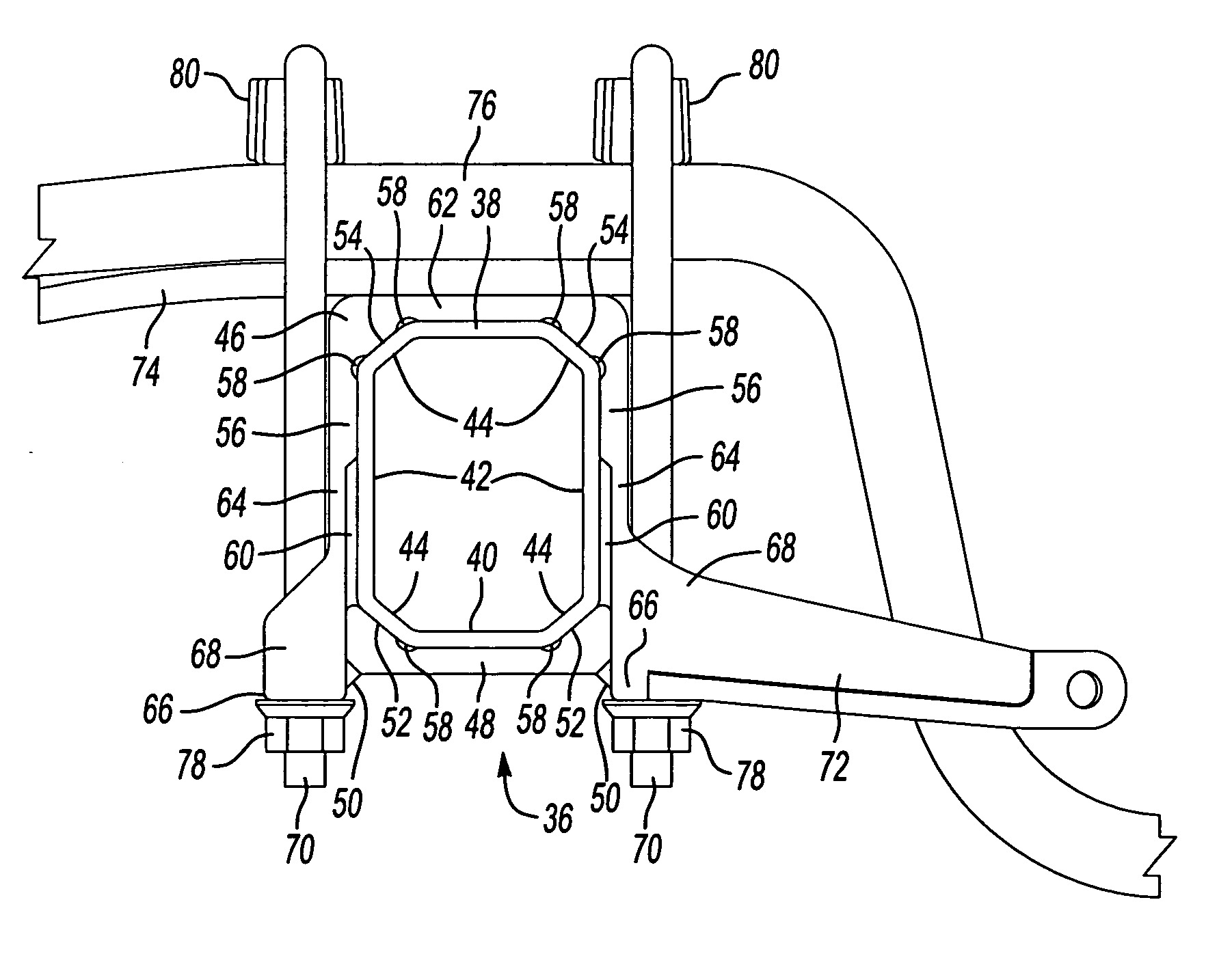
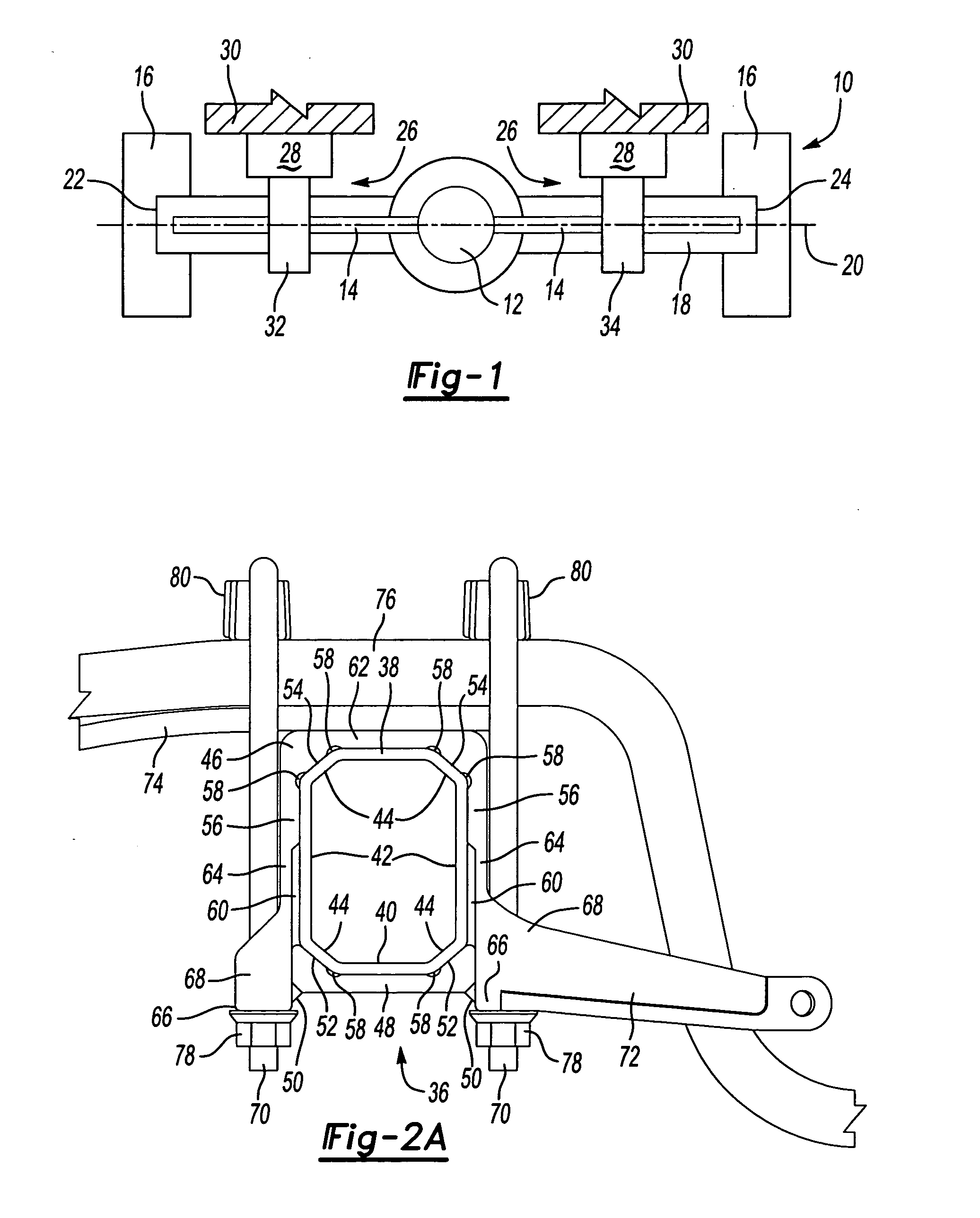
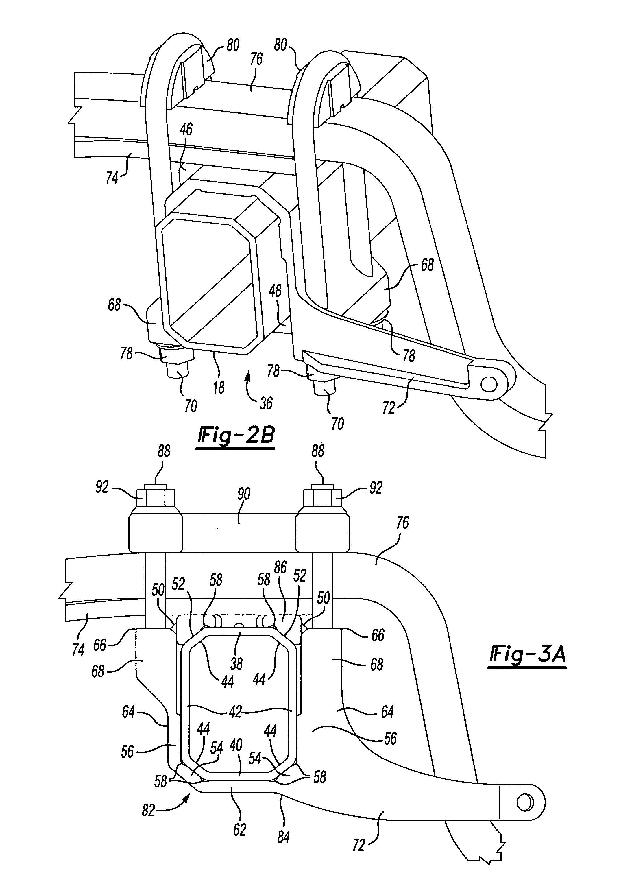
[0017] An axle assembly is shown generally at 10 in FIG. 1. The axle assembly 10 is preferably a drive axle including a center differential 12 that drives a pair of axle shafts 14. The axle shafts 14 drive wheel end assemblies 16 that support tires (not shown). The axle assembly 10 includes an axle housing 18 that substantially encloses the axle shafts 14 and the differential 12. The axle housing 18 defines a lateral axis 20 and includes a first leg portion 22 extending to one wheel end assembly 16 and a second leg portion 24 extending to the other wheel end assembly 16.

[0018] A suspension mount interface, shown generally at 26, is used to mount the axle assembly 10 to a vehicle suspension 28. The suspension 28 is supported by a vehicle frame 30. The suspension mount interface 26 includes a first bracket assembly 32 positioned at the first leg portion 22 and a second bracket assembly 34 positioned at the second leg portion 24. The bracket assemblies 32, 34 connect the axle assembly...


PUM


Abstract

An axle housing includes a suspension mount interface for mounting a vehicle suspension to the axle housing. The axle housing includes a first leg portion extending to a first wheel assembly and a second leg portion extending to a second wheel assembly. The first and second leg portions each include a suspension mount interface. Each suspension mount interface includes first and second bracket portions. The first and second bracket portions are clamped together prior to attachment to the axle housing to form a suspension bracket assembly. One clamped suspension bracket assembly is then slid over each axle housing leg portion. The first and second bracket portions are subjected to a preload force as they are welded or fastened to each other, providing a preload effect to define a suspension load path that has positive contact only at desired locations on the axle housing.

Description

BACKGROUND OF THE INVENTION [0001] The subject invention generally relates to a suspension bracket assembly for a vehicle axle housing that is preloaded during attachment to control transfer of the load path from an input to the suspension. [0002] Medium and heavy duty vehicles include suspensions that are attached to axle housings in various different manners. Traditionally, these suspensions include loose piece brackets that are welded to the axle housing, or are clamped to the axle housing to define a suspension mount interface. A conventional loose piece suspension mount interface includes an upper bracket positioned between an upper surface of the axle housing and a suspension main support member and a lower bracket positioned underneath the axle housing. A pair of U-bolts extends over the suspension main support member and are fastened against the lower bracket underneath the axle housing. [0003] This suspension mount interface creates many design challenges. There are a varie...

Claims


Application Information

Patent Timeline
Patent Type & Authority Applications(United States)
IPC IPC(8): B60G7/00B60B35/00B60G9/00B60G9/02B60G9/04B60G11/10B60G11/113
CPCB60G9/003B60G11/113B60G2200/31B60G2206/32B60G2204/121B60G2204/148B60G2204/4306B60G2202/112
Inventor PAN, JAW-PINGSMITH, MARKTROST, HARRY W.BULEY, THOMAS D.ESCHENBURG, DALE J.BRAGAN, PAUL G.SOMMAY, RAJESH J.LIE, TIONG T.MCKENZIE, JACK R.HALL, EVERETT
Owner ARVINMERITOR TECH
Why Eureka
Try Eureka