Rim structure particularly for cycle wheel with variable magnetic field electric generator

a technology of variable magnetic field and electric generator, which is applied in the direction of bicycle equipment, optical signals, transportation and packaging, etc., can solve the problems of discontinuity in the succession of permanent magnets, the voltage generated is dependent on the speed of bicycle movement, and the efficiency reduction

Inactive Publication Date: 2005-11-17
GLOW SRL
View PDF6 Cites 7 Cited by
  • Summary
  • Abstract
  • Description
  • Claims
  • Application Information

AI Technical Summary

Benefits of technology

[0013] A main object of the present invention is that of overcoming the abovementioned drawbacks by providing a rim structure which eliminates or substantially reduces the known problems associated with the supply of electricity to bicycles using current generators of the variable magnetic field type.
[0016] A further object of the invention is that of providing a structure which is able to protect the permanent magnets from dirt or accidental damage, preventing any dislodging or loss of efficiency of the said magnets during use.
[0017] Another particular object is that of providing a structure which is simple and economically advantageous in that it can be manufactured at a low cost using technology of the known type.
[0021] Owing to this particular rim structure and manufacturing method it will be possible to use a large number of permanent magnets and to arrange them in a safe and reliable manner, avoiding undesirable movement or vibration thereof.

Problems solved by technology

In addition to the problems associated with deterioration of the moving parts which reduce the efficiency of the dynamo and cause a bothersome noise, the dynamo has the major disadvantage that the voltage which is generated is dependent upon the speed of movement of the bicycle.
This solution, however, also has problems associated in particular with the fact that there is a discontinuity in the succession of permanent magnets, since the curved segments are themselves arranged circumferentially spaced on the spokes.
The magnets are moreover not protected since they are arranged on curved segments which, being independent components on the outside of the bicycle wheel, may be moved, damaged and lost, being separated from the wheel itself.
However, the insertion of the permanent magnets into said side pocket at regular distance with respect to each other is rather difficult and unreliable, and does not prevent undesirable movements or vibrations of the magnets.

Method used


Image

  • Rim structure particularly for cycle wheel with variable magnetic field electric generator
  • Rim structure particularly for cycle wheel with variable magnetic field electric generator
  • Rim structure particularly for cycle wheel with variable magnetic field electric generator

Examples


Embodiment Construction

)

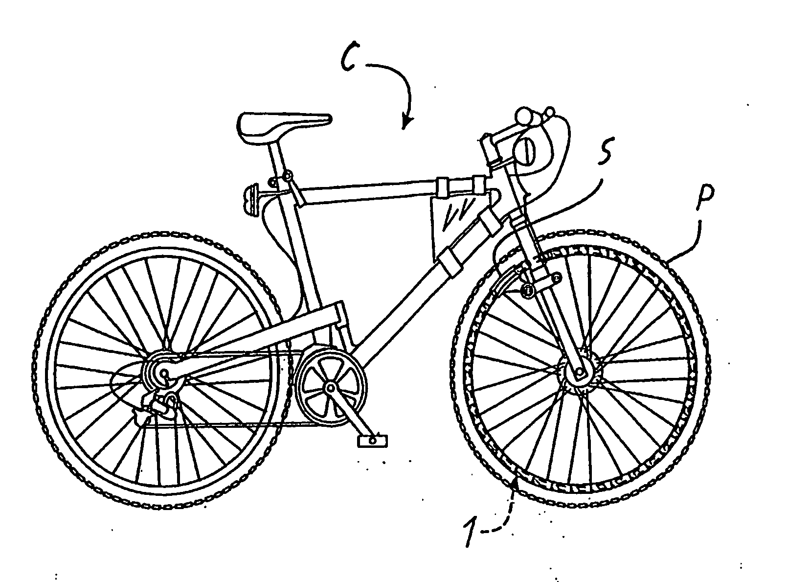
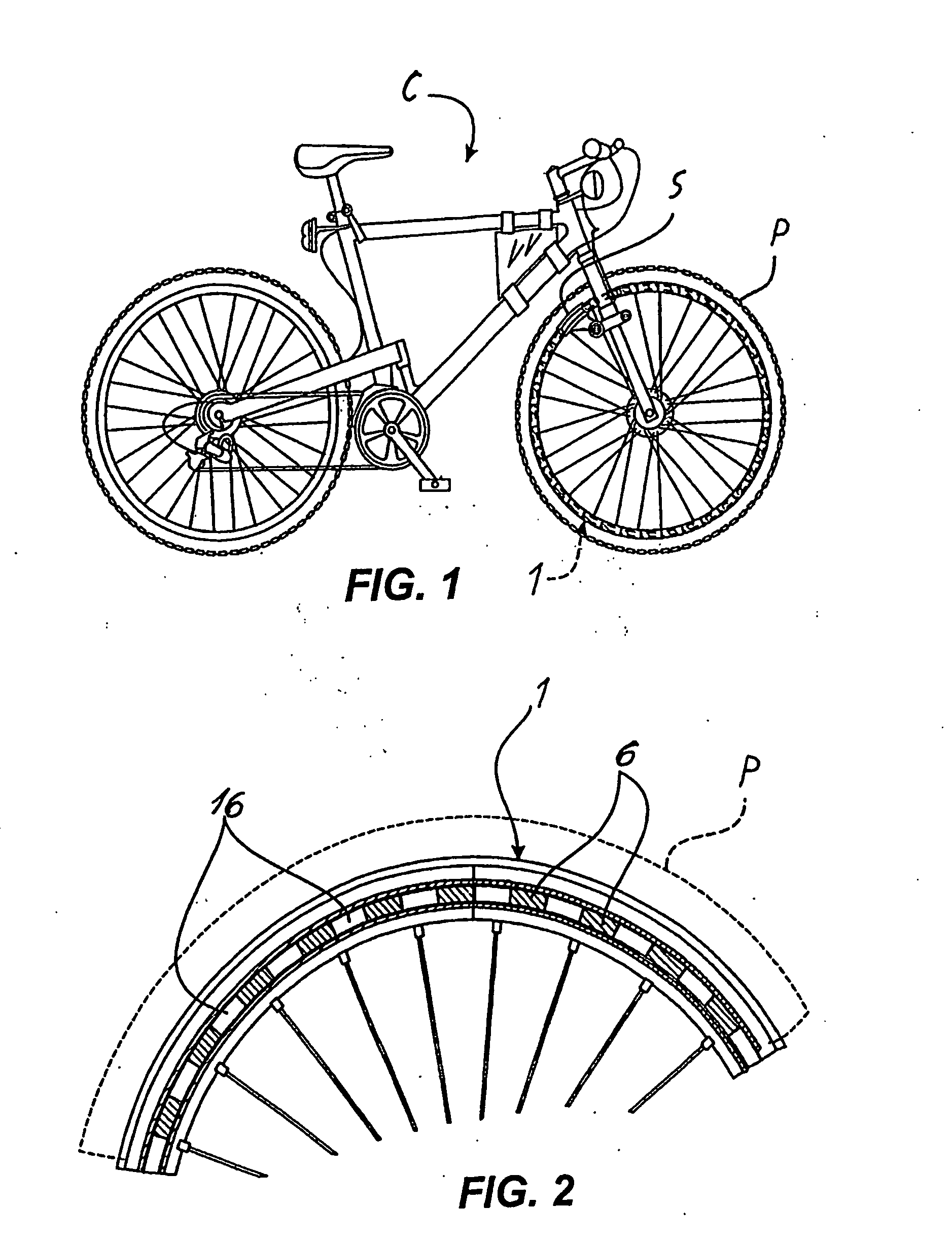
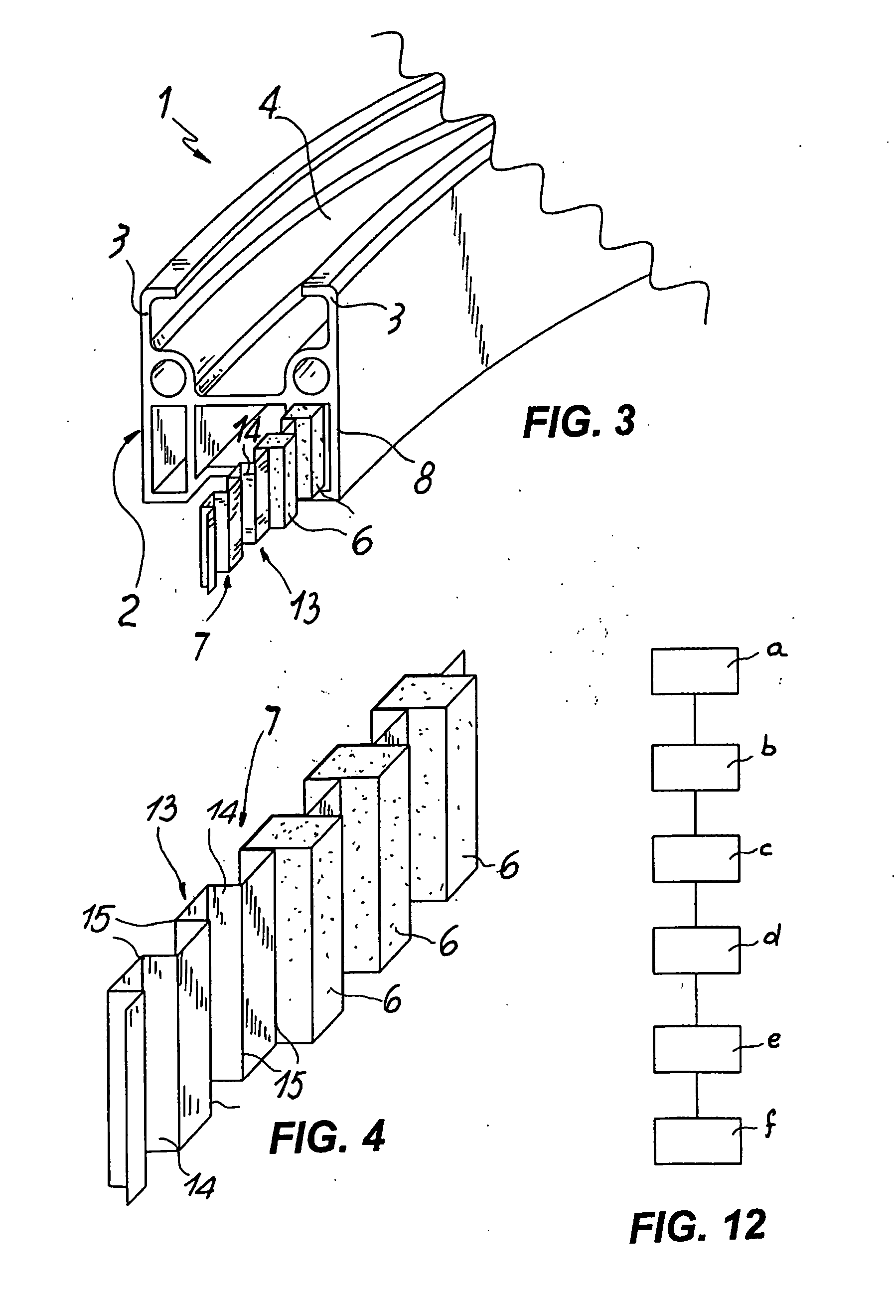
[0032] With particular reference to the above mentioned figures, a rim structure is shown according to the invention, denoted in its entirety by the reference number 1.

[0033] The rim structure 1 is mounted on a bicycle C equipped with a current generator of the variable magnetic field type, known per se.

[0034] The rim 1 comprises a peripherally or circumferentially extending tubular body—denoted in its entirety by the reference number 2—from which a pair of opposite flanges 3 defining a seat 4 for housing a tyre P extends outwards.

[0035] According to the invention, the tubular body 2 comprises at least one annular peripheral side pocket 5 which is able to house a plurality of permanent magnets 6 aligned along a circumference. Moreover, spacer means, denoted overall by the reference number 7, are envisaged, said spacer means being inserted inside the side pocket 5 so as to keep the permanent magnets 6 suitably directed and situated at predetermined distances from each other.

[003...


PUM

PropertyMeasurementUnit
magnetic fieldaaaaaaaaaa
relative distancesaaaaaaaaaa
axis of rotationaaaaaaaaaa

Abstract

A rim structure, in particular for bicycles equipped with a current generator of the variable magnetic field type, comprises a circumferentially extending tubular body (2) from which a pair of opposite flanges (3) defining a seat (4) for housing a tyre (P) extends outwards. According to the invention the tubular body (2) comprises at least one annular peripheral side pocket (5) able to house a plurality of permanent magnets (6) aligned along one circumference. Spacer means (7) are also envisaged, said means being inserted in the side pocket (5) in order to keep the permanent magnets (6) at predetermined distances from each other.

Description

TECHNICAL FIELD [0001] The present invention is generally applicable in the field of wheeled vehicles and, in particular, relates to a rim structure, in particular for bicycles equipped with a current generator, as well as to a method and a machine for manufacturing this structure. BACKGROUND ART [0002] As is known, in bicycles where an available supply of electricity is required in order to power applications such as the front light and rear light, generators—commonly referred to as “dynamos”—are used, said generators being essentially alternators which receive the driving movement from a knurled roller which is arranged so as make contact, via spring means, with one of the tyres of the bicycle. [0003] In addition to the problems associated with deterioration of the moving parts which reduce the efficiency of the dynamo and cause a bothersome noise, the dynamo has the major disadvantage that the voltage which is generated is dependent upon the speed of movement of the bicycle. [000...

Claims


Application Information

Patent Timeline
Patent Type & Authority Applications(United States)
IPC IPC(8): B60B21/02B60B21/06B60B21/00B62J6/06
CPCB60B5/02B60B21/023B60B21/025B60B21/04Y10T29/49009B60B21/12B60B25/02B62J6/06B60B21/062
Inventor ZAMPIERI, DANIELE
Owner GLOW SRL
Why Eureka
Try Eureka