Radio remote control system

Inactive Publication Date: 2005-11-17
RINNAI CORP
View PDF4 Cites 26 Cited by
  • Summary
  • Abstract
  • Description
  • Claims
  • Application Information

AI Technical Summary

Benefits of technology

[0016] According to the invention described above, the state switching means switches the radio remote controller to the data receivable state when the transmission of the operation instruction data by the radio remote controller ends in the data transmittable state. Therefore, when the controlled apparatus transmits new monitor data at the time when predetermined processing applied to the operation instruction data ends to the radio remote

Problems solved by technology

However, the water heater main body does not grasp time when the power supply is turned off.
Therefore, it is difficult to easily and flexibly change time for keeping power supply to the reception circuit of the radio remote con

Method used


Image

  • Radio remote control system
  • Radio remote control system
  • Radio remote control system

Examples


Embodiment Construction

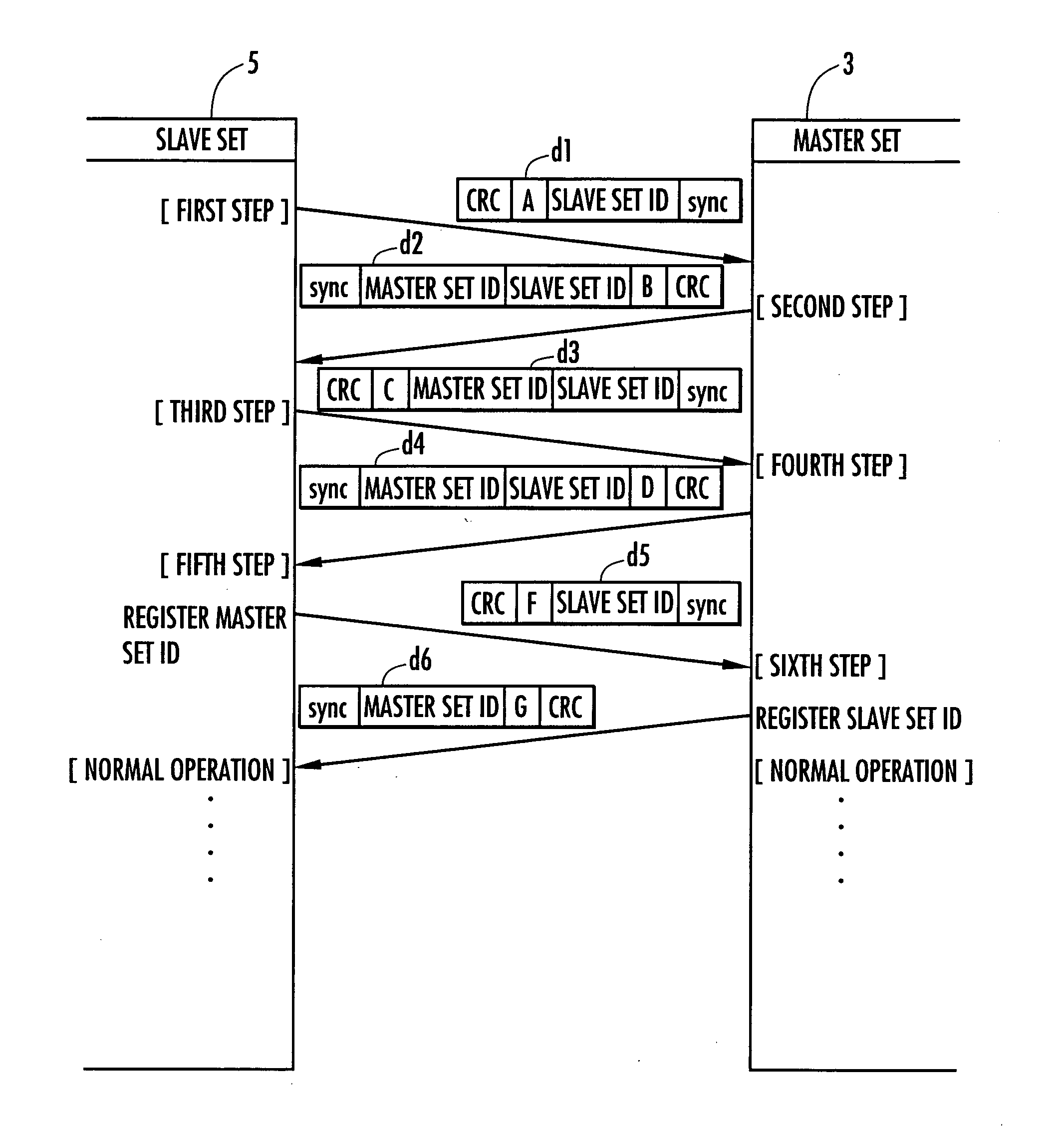
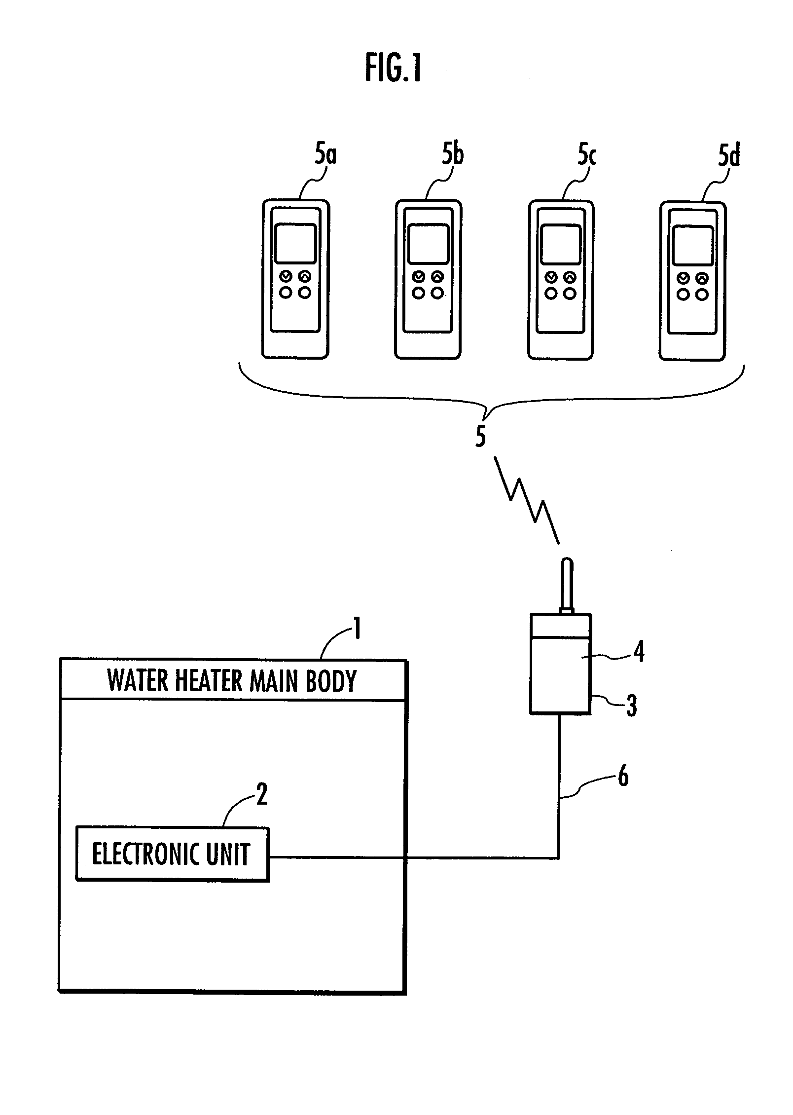
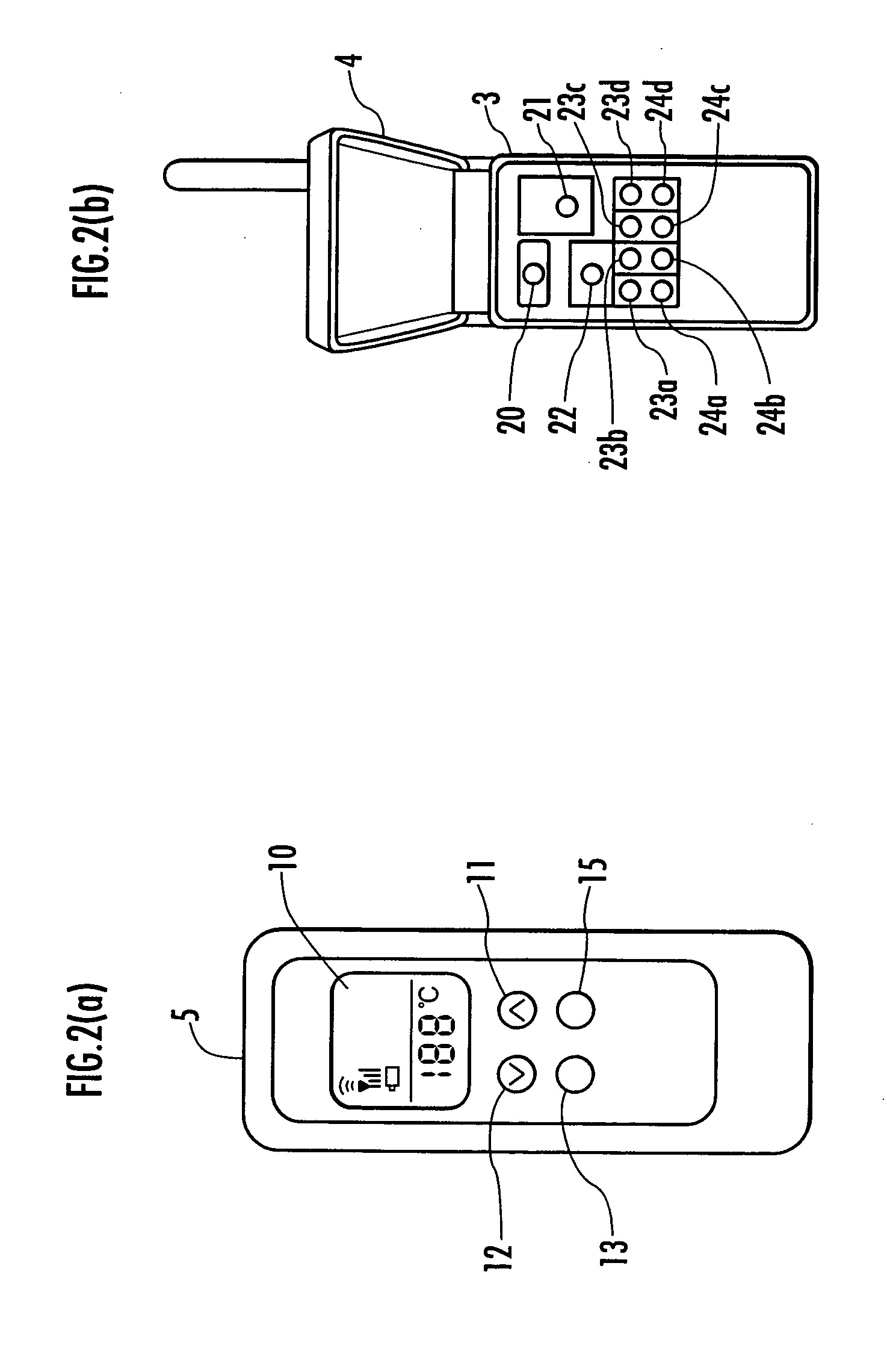
[0025] An embodiment of the invention will be hereinafter explained with reference to the accompanying drawings. FIG. 1 is an overall diagram of a hot water supply system serving as a radio remote control system of the invention. FIG. 2A is an external view of a slave set shown in FIG. 1. FIG. 2B is an external view of a master set shown in FIG. 1. FIG. 3A is a diagram of the master set shown in FIG. 1. FIG. 3B is a diagram of the slave set shown in FIG. 1. FIG. 4 is a diagram explaining transmission and reception states of data between the master set and the slave set at the time when the pairing processing is executed. FIG. 5 is a timing chart of data communication between the master set and the slave set at the time when monitor data is transmitted from the master set. FIG. 6 is a timing chart of data communication between the master set and the slave set at the time when a switch of the slave set is operated.

[0026] Referring to FIG. 1, a water heater main body 1 is controlled b...


PUM


Abstract

It is an object of the invention to provide a radio remote controller system that, when power saving for a radio remote controller is realized by intermittently setting a data receivable period in the radio remote controller, can easily and flexibly change a length of a period for making it impossible to receive the radio data and reduce power consumption of the radio remote controller. A master set connected to a water heater main body by wire transmits monitor data G(G1, G2, G3) indicating an operation state of the water heater main body, which include transmission time information indicating the next time (t14 at G1, and t17 at G2) of transmission of the monitor data G, to a slave set serving as a radio remote controller. The slave set, which has received the monitor data G, comes into a “standby state” (slave set Rx and slave set Tx are OFF), in which power consumption is smaller than “data receivable state” (a slave set Rx is ON) and transmission and reception of radio data are impossible, until the next time of transmission of the monitor data G acquired from the monitor data (Toff1, Toff2, Toff3). When start time (t13, t16) for reception of monitor data has come, the slave set is switched from the “standby state” to the “data receivable state” to receive the monitor data G.

Description

BACKGROUND OF THE INVENTION [0001] 1. Field of the Invention [0002] The present invention relates to a system that remotely controls a controlled apparatus using a radio remote controller and, more particularly, to power saving for the radio remote controller in the case in which monitor data is transmitted to the radio remote controller from the controlled apparatus. [0003] 2. Description of the Related Art [0004] As an example of a system that remotely controls a controlled apparatus using a radio remote controller, there is known a hot water supply system that is adapted to remotely control a water heater main body using a radio remote controller. In the hot water supply system, power is supplied to a reception unit of the radio controller intermittently to realize power saving for the radio remote controller (see, for example, Japanese Patent Application Laid-Open No. 4-192996). [0005] In such a hot water supply system, when a switch of the radio remote controller is operated, a...

Claims


Application Information

Patent Timeline
IPC IPC(8): F24H1/00F24D19/10G05B23/02G05D23/00H04Q9/00
CPCG05B19/042Y02B60/50G05B2219/25289H04Q9/00H04Q9/04
Inventor KATO, KEIJIADACHI, IKURO
Owner RINNAI CORP
Why Eureka
Try Eureka