Ink-jet printer

a technology of inkjet printers and inkjet printers, applied in the direction of printing, etc., can solve the problems of difficult positioning, etc., and achieve the effect of convenient operation, easy opening and closing, and convenient opening and closing

Active Publication Date: 2005-11-17
BROTHER KOGYO KK
View PDF6 Cites 21 Cited by
  • Summary
  • Abstract
  • Description
  • Claims
  • Application Information

AI Technical Summary

Benefits of technology

[0056] The above-indicated third advantageous form is an effective form of the second aspect of the invention where the ink-jet printer performs the recording operation using a plurality of inks. It is noted that “a space located around the operating member” may be interpreted that the space is included in the outer space indicated above. According to the third advantageous form, the operating member is moved in the direction of extension of the at least two of the plurality of air-discharge passages by the movable member of the second moving device, whereby the at least two of the air-discharging valve devices can be simultaneously opened and closed with ease. Moreover, by the execution of the second discharge operation, the inside in the at least two air-discharging valve devices and the space around the operating member are exhausted, so that the ink remaining in the inside of the at least two air-discharging valve devices and on the operating member can be removed.
[0057] In the third advantageous form described above, the casing preferably has a guide hole portion and the operating member preferably has an engaging portion which slidably engages the guide hole portion. In this arrangement, the engaging portion of the operating member slidably engages the guide hole portion of the casing, whereby the operating member is moved while being guided owing to the engagement of the engaging portion and the guide hole portion. Hence, the at least two air-discharging valve devices can be smoothly placed in the valve-open state and the valve-close state.
[0058] Preferably, the engaging portion is disposed at a middle of the operating member. In this arrangement, because the engaging portion which guides the movement of the operating member is disposed at a middle of the operating member, the operating member is prevented from inclining during the movement thereof.
[0059] Preferably, the guide hole portion is formed with an atmosphere communication hole which is arranged to be closed at the time of execution of the first discharge operation and opened at the time of execution of the second discharge operation for introducing the atmosphere into the outer space. In this arrangement, because the atmosphere communication hole that is arranged to be closed at the time of execution of the first discharge operation is formed in the guide hole portion, the atmosphere can be easily introduced through the atmosphere communication hole at the time of execution of the second discharge operation, without influencing the first discharge operation.
[0060] Preferably, the atmosphere communication hole is closed in the valve-open state of the at least two of the plurality of air-discharging valve devices and opened in the valve-close state thereof by an operation of the valve opening-and-closing device. In this arrangement, the atmosphere communication hole can be easily opened and closed.
[0061] In the above-indicated third advantageous form, the operating member is preferably provided to correspond to all of the plurality of air-discharging valve devices and preferably has a plurality of operating portions that respectively correspond to the valve members of the plurality of air-discharging valve devices. In this arrangement, all of the plurality of air-discharging devices can be easily operated.

Problems solved by technology

However, this positioning is rather difficult.

Method used


Image

  • Ink-jet printer
  • Ink-jet printer
  • Ink-jet printer

Examples


first embodiment

[0105] Referring next to FIGS. 6-9, there will be explained in detail the air-discharging valve devices 15, constructed according to the invention, for discharging the air separated from the ink in the storage chambers 31a-31d of the buffer tank 14 and introduced through the discharge-air introducing passages 41a-41d.

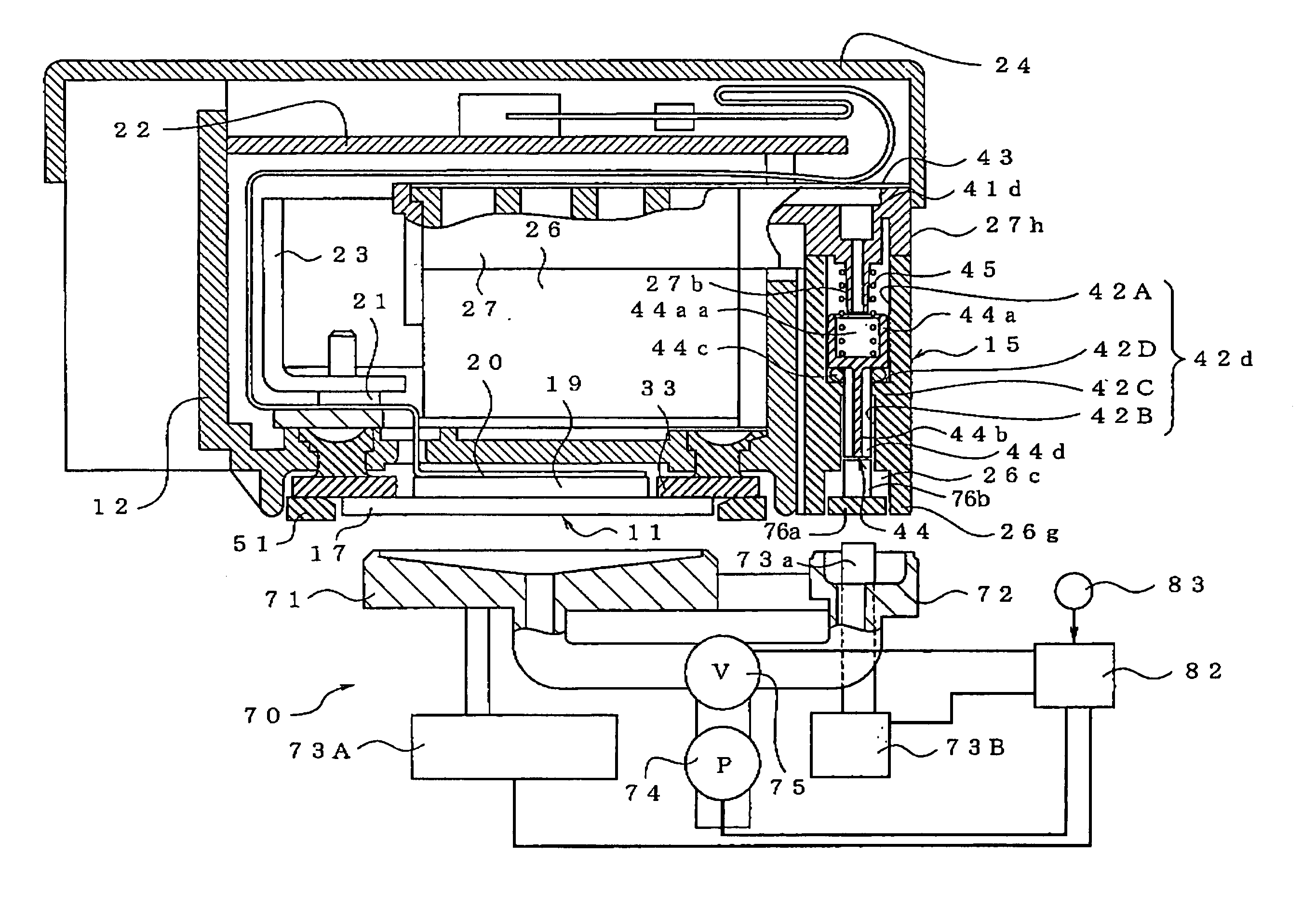
[0106] The plurality of air-discharging valve devices 15 have an outer contour that is provided by a casing common to all of the air-discharging valve devices. More specifically described, the casing is constituted by a lower valve casing portion 26g which is formed integrally on one side of the lower casing member 26 and an upper valve casing portion 27h which is formed integrally on one side of an upper casing member 27 to extend therefrom for covering an upper section of the lower casing valve portion 26g. Four air-discharge holes 42a-42d each of which constitutes an air-discharge passage are formed in the lower valve casing portion 26g. The four air-discharge holes...

fourth embodiment

[0136] The operating members 76′″, 86 are not necessarily provided with the respective push-up-pin portions 76b′″, 86b. Described in detail with respect to the fourth embodiment shown in FIG. 13, the rod portions 44b may be configured such that the lower end portions thereof extend beyond the outlets (the lower end openings) of the corresponding air-discharge holes 42a-42d, and the lower end portions of the rod portions 44b may be pushed up by the upper surfaces of the base portions of the operating members 76′″, 86.

[0137] Referring next to FIG. 14, there will be explained a fifth embodiment of the invention in which the same or similar reference numerals as used in any of the illustrated first through fourth embodiments are used to identify the corresponding components, and a detailed explanation of which is omitted.

fifth embodiment

[0138] The operating member is not necessarily provided on the lower valve casing portion side (26g), i.e., on the carriage side (12). For instance, in the fifth embodiment shown in FIG. 14, the operating members 76″″, 86′ are connected respectively to one ends (the upper ends) of the movable members 73a, 84 nearer to the air-discharging valve devices. In this embodiment, too, when the carriage 12 is moved to the stand-by position, the movable members 73a, 84 are opposed to the lower ends of the rod portions 44b via the operating members 76″″, 86′ and the air-discharging valve devices 15 are placed in the valve-open state by moving the movable members 73a, 84 upwards.

[0139] While the preferred embodiments of the present invention have been described in detail by reference to the drawings, it is to be understood that the present invention may be otherwise embodied.

[0140] Each of the illustrated embodiments is explained with respect to a case wherein the valve member 44 of each air-d...


PUM


Abstract

An ink-jet printer including: a buffer tank; an air-discharging valve device; and a valve opening-and-closing device. The ink-jet printer father includes an operating member which is arranged to be interposed between the air-discharging valve device and the valve opening-and-closing device. The valve opening-and-closing device operates the air-discharging valve device via the operating member, such that the air-discharging valve device is placed in a valve-open state and a valve-close state. The ink-jet printer is arranged to execute a first discharge operation in which the air separated from the ink in the buffer tank is discharged while placing the air-discharging valve device in the valve open state, and a second discharge operation in which an inside of the air-discharging valve device is exhausted to remove the ink remaining in the air-discharging valve device while placing the air-discharging valve device in the valve-close state.

Description

[0001] This application is based on Japanese Patent Application Nos. 2004-142541 and 2004-142542 filed on May 12, 2004, the contents of which are incorporated hereinto by reference. BACKGROUND OF THE INVENTION [0002] 1. Field of the Invention [0003] The present invention relates to an ink-jet printer, in particular, an ink-jet printer capable of accumulating bubbles separated from ink in an ink path and discharging the bubbles. [0004] 2. Discussion of Related Art [0005] To assure a reduction in the size (the thickness) of an ink-jet printer, there is a demand for a reduction in the size (the thickness) of a carriage of the printer, in other words, there is a demand that the inkjet printer is constructed in such a way that an ink tank which accommodates ink is not installed on the carriage. To this end, the ink tank needs to be provided outside of the carriage, e.g., on a frame of the printer, and the ink in the ink tank needs to be supplied, via an ink supply tube, to a recording he...

Claims


Application Information

Patent Timeline
Patent Type & Authority Applications(United States)
IPC IPC(8): B41J2/175B41J2/19
CPCB41J2/175B41J2/19B41J2/17596B41J2/17509
Inventor USUI, TAKAMASA
Owner BROTHER KOGYO KK
Why Eureka
Try Eureka