Image sensor module

Inactive Publication Date: 2005-11-17
ROHM CO LTD
View PDF13 Cites 48 Cited by
  • Summary
  • Abstract
  • Description
  • Claims
  • Application Information

AI Technical Summary

Benefits of technology

[0005] An object of the present invention is to provide an image se

Problems solved by technology

The view angle when imaging the subject (the area of the subject which may be obtained as an image through the lens) is fixed and diversity in imaging is limited.
However, a zoom lens unit has a precision mechanism to move a simple lens accurately, and cost is therefor

Method used


Image

  • Image sensor module
  • Image sensor module
  • Image sensor module

Examples


Example

[0047] The desirable embodiments of the present invention are hereunder described detail in reference to the figures.

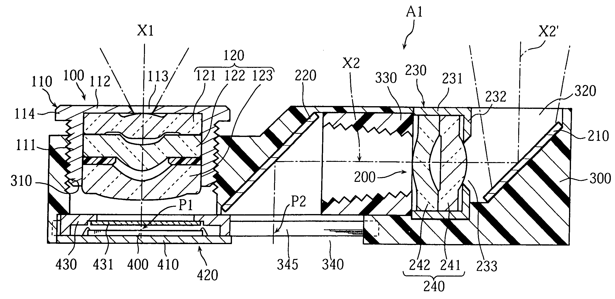
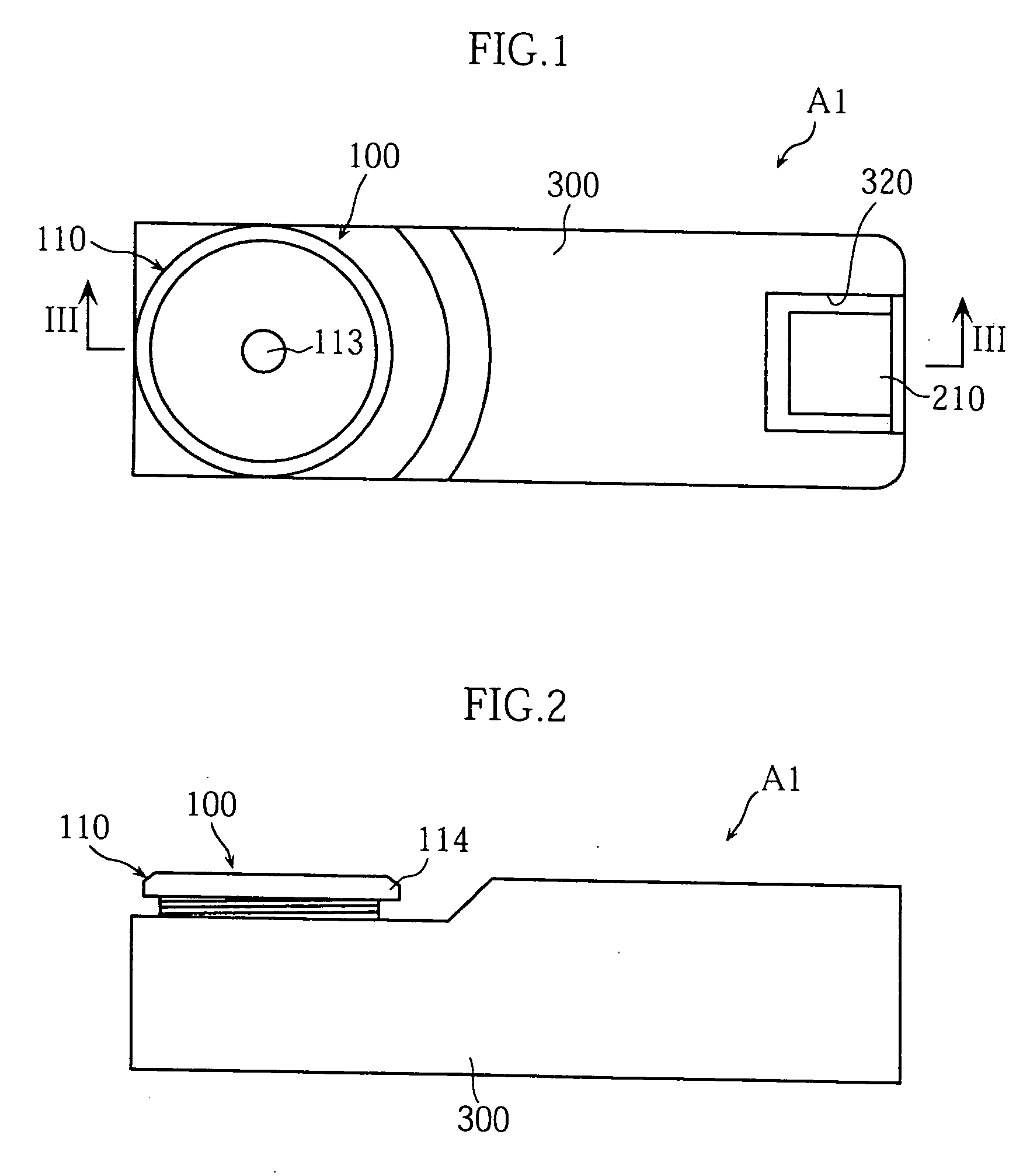
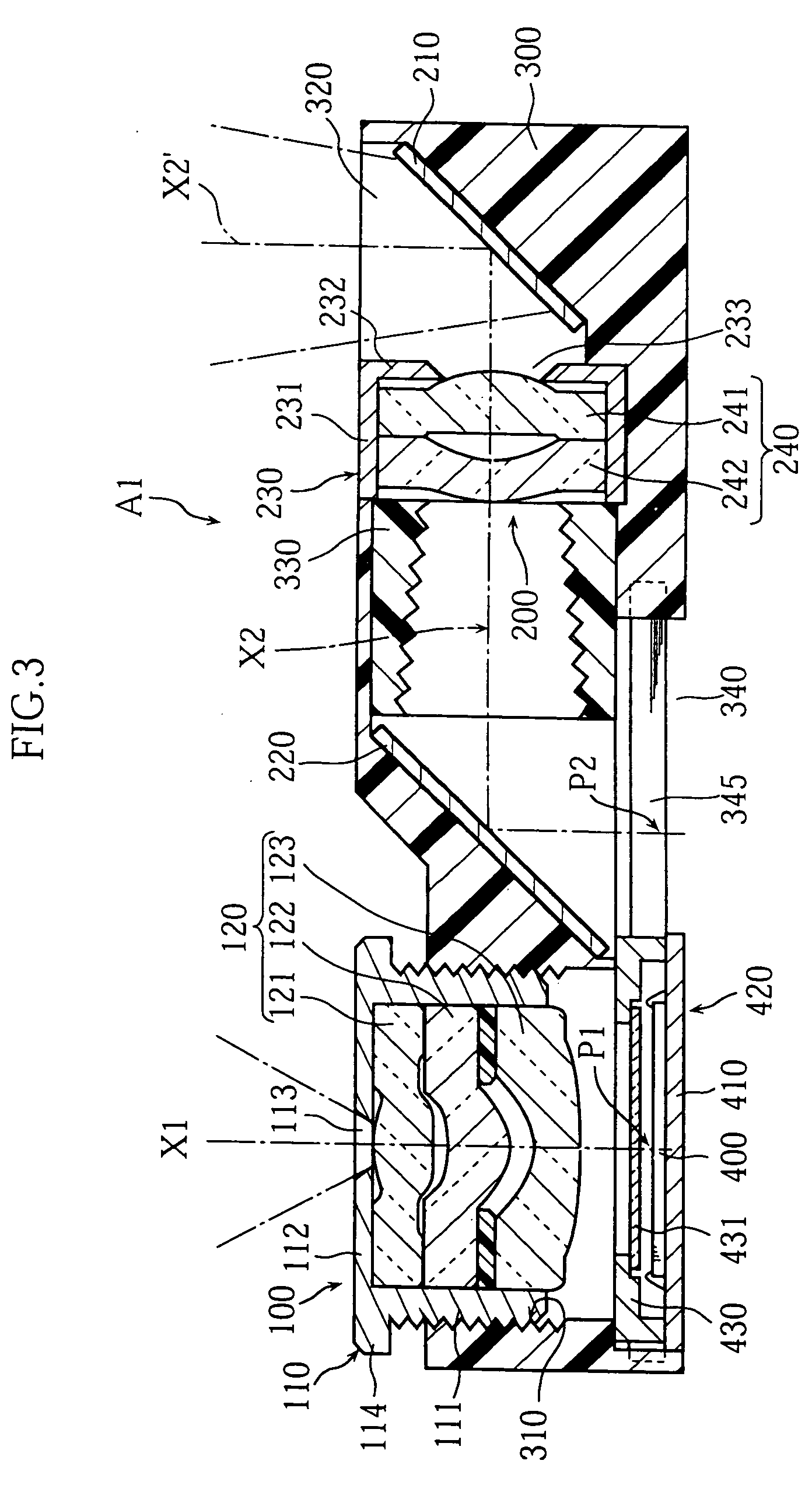
[0048]FIG. 1 through FIG. 4 show embodiments of the image sensor module according to the present invention. As clearly shown in FIG. 3, the image sensor module A1 of the present embodiment is comprised of a case 300, first and second optical units 100 and 200, an image sensor chip 400, and an operating mechanism 420.

[0049] The case 300 is of synthetic resin, and is rectangular in shape in plan view. The first optical unit 100 is provided at one end in the longitudinal direction of the case 300, and has an image-forming lens 120. This image-forming lens 120 is a compound lens comprising three simple lenses 121, 122, and 123 stacked together within a cap 110. The simple lenses 121 and 122 are convex lenses, while the simple lens 123 is a concave lens. According to this structure, distortion can be reduced, and achromatization is also possible. The cap 110 has a tubula...


PUM


Abstract

An image sensor module A1 includes a case 300, a photoelectric converter 400 positioned within the case 300, and first and second optical units 100, 200 for forming an image of a subject on the light-receiving surface of the photoelectric converter 400. Imaging of the subject using the first optical unit 100, or imaging of the subject using the second optical unit 200, can be selected. It is possible to conduct a plurality of types of imaging each having a different view angle, while restricting increases in size and cost.

Description

TECHNICAL FIELD [0001] The present invention relates to an image sensor module employed as a component in digital cameras, and mobile phones with cameras and the like. BACKGROUND ART [0002] An example of this type of image sensor module is disclosed in JP-A 2002-247288. The image sensor module disclosed in this publication comprises an image sensor chip mounted on a substrate, and a case enclosing the image sensor chip on the upper surface of the substrate. The case holds an image-forming lens firmly in place. The image of the subject is formed on the image sensor by the function of the image-forming lens. The image sensor chip outputs an image signal with an output level corresponding to the image of the subject. [0003] However, the conventional technology has only a single optical unit employing an image-forming lens, while the focal distance of the image-forming lens is fixed. The view angle when imaging the subject (the area of the subject which may be obtained as an image throu...

Claims


Application Information

Patent Timeline
IPC IPC(8): G03B17/17G03B11/00H04N5/225H04N5/335H04N5/372
CPCH04N5/2254H04N5/2253H04N23/55H04N23/54H04N23/00H04N25/00
Inventor FUJIMOTO, HISAYOSHIIMAMURA, NORIHIRO
Owner ROHM CO LTD
Why Eureka
Try Eureka