Lens apparatus and optical apparatus equipped with same

Active Publication Date: 2005-11-17
CANON KK
View PDF3 Cites 17 Cited by
  • Summary
  • Abstract
  • Description
  • Claims
  • Application Information

AI Technical Summary

Benefits of technology

[0013] In view of the above circumstances, an object of the present invention is to achieve a reduction in the total length of a lens in

Problems solved by technology

Accordingly, there is a risk that these portions can interfere with the lens barrel member of the magnification changing lens (or the first and second lens units) driven along the optical axis by the cam ring, and therefore it is difficult to reduce the total length of the lens in the collapsed state.
However, this method sometimes invites entrance of undesirable light onto the image pickup element through the opening.
Accordingly, it is dif

Method used


Image

  • Lens apparatus and optical apparatus equipped with same
  • Lens apparatus and optical apparatus equipped with same
  • Lens apparatus and optical apparatus equipped with same

Examples


Embodiment Construction

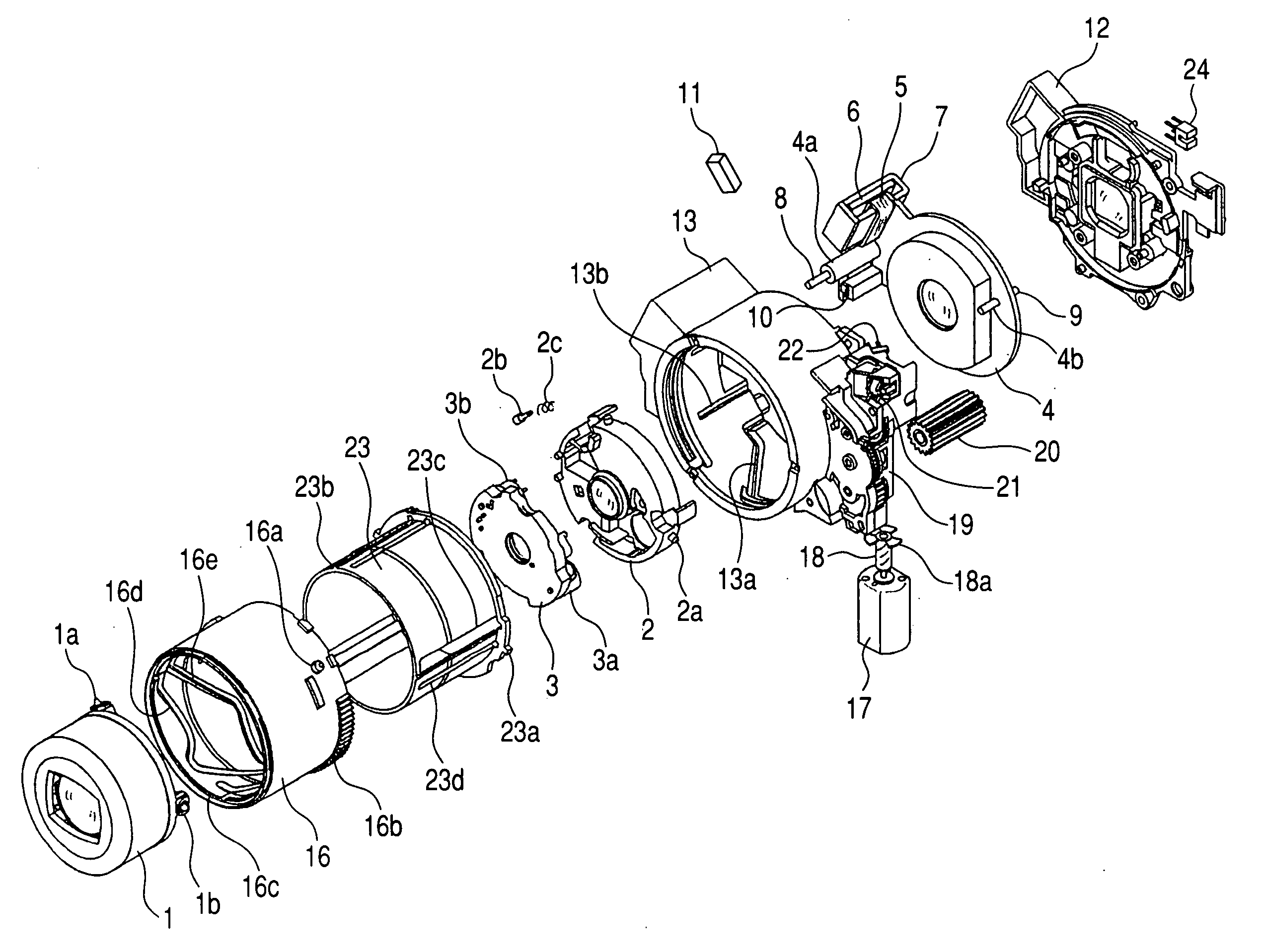
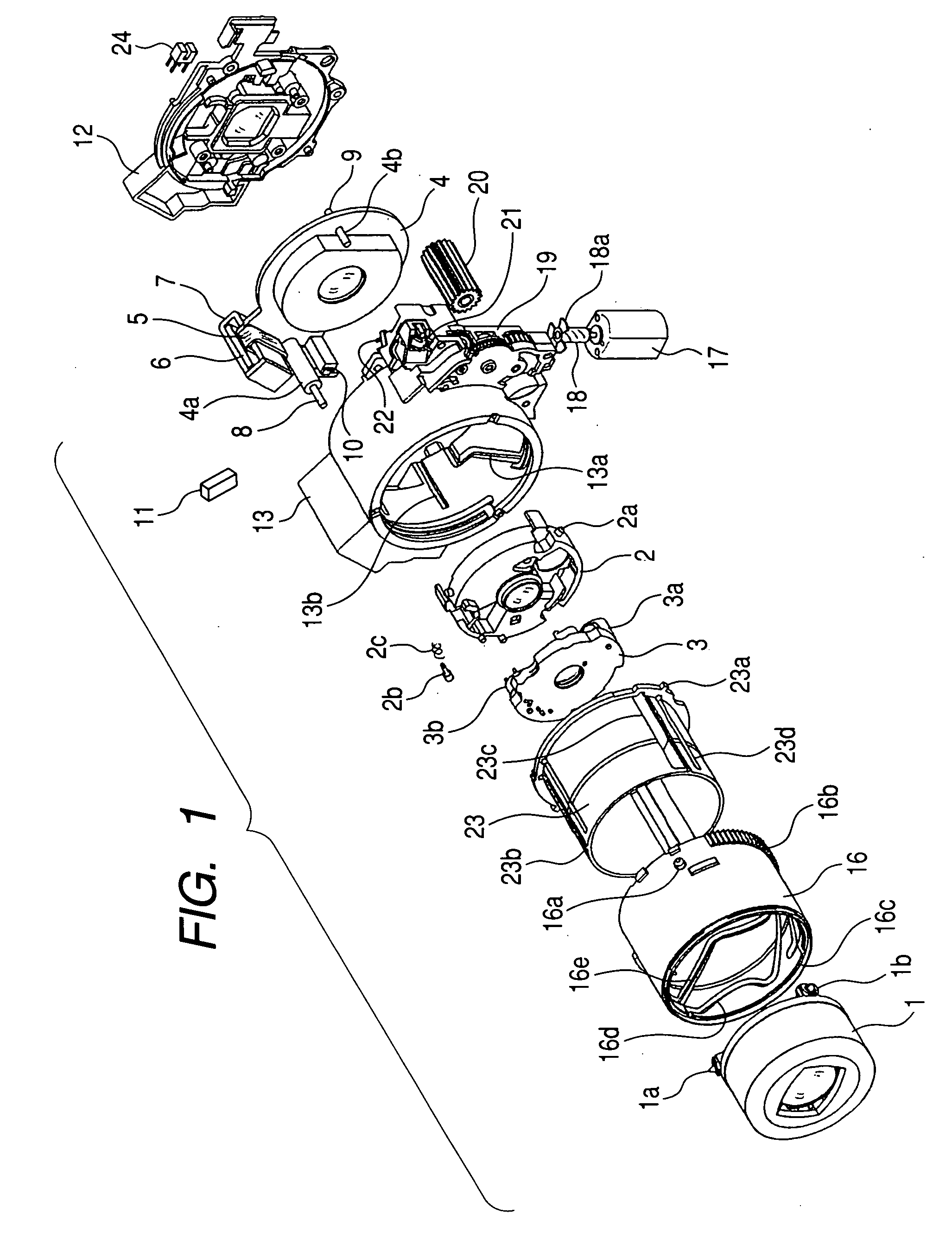
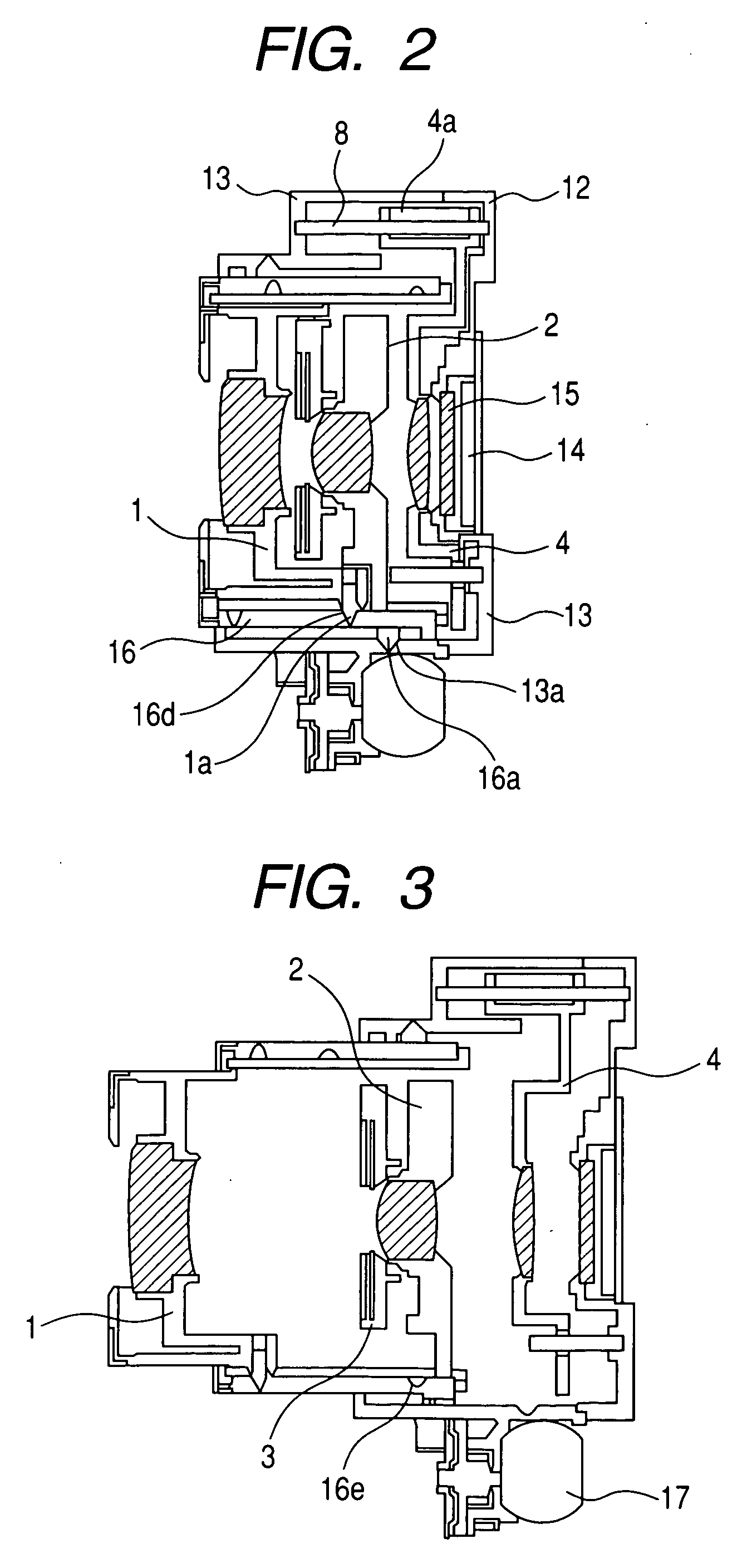
[0024]FIG. 1 is a perspective view showing a lens barrel according to an embodiment of the present invention. FIGS. 2 and 3 are cross sectional views of the lens barrel of this embodiment. FIG. 2 shows the collapsed state in which image taking is not allowed, and FIG. 3 shows the extended state in which image taking is allowed.

[0025] The lens barrel (lens apparatus) of this embodiment is a zoom lens barrel in which a zoom optical system including three lens units are held.

[0026] The zoom optical system of this embodiment is a three-unit zoom optical system of a rear focus type composed of a lens unit having a negative refractive power, a lens unit having a positive refractive power and a lens unit having a positive refractive power arranged in the mentioned order from the object side to the image side, wherein zooming is effected by means of the first lens unit and the second lens unit, while focusing is effected by means of the third lens unit.

[0027] In FIGS. 1 to 3, reference n...


PUM


Abstract

The present invention provides a lens apparatus including a fixed lens barrel, a cam ring that is rotatable relative to the fixed lens barrel, a first lens holding frame adapted to move, upon rotation of the cam ring, relative to the fixed lens barrel along the optical axis direction over the range from a collapsed position in which image taking is not allowed to an extended position in which image taking is allowed, a second lens holding frame disposed on the image side of the first lens holding frame, and a linear driving portion disposed outside the cam ring, for driving the second lens holding frame along the optical axis direction using a coil and a magnet. The length of the lens apparatus is relatively short and it is advantageous in portability.

Description

BACKGROUND OF THE INVENTION [0001] 1. Field of the Invention [0002] The present invention relates to a lens apparatus (or a lens barrel) and an optical apparatus equipped with the same, which are suitably applied to optical apparatuses such as still cameras, digital still cameras and video cameras. [0003] 2. Related Background Art [0004] Various lens barrels of the collapsible type have been conventionally proposed. In the collapsible type lens barrel, a lens barrel member such as a lens holding frame that holds a lens(es) is moved toward the camera body to reduce its length along the optical axis to thereby improve portability. [0005] Japanese Patent Application Laid-Open No. 2001-324663 discloses a mechanism, used in a lens barrel of the collapsible type, that drives a focusing lens (the third lens unit) along the optical axis direction while effecting position control. This mechanism is adapted to drive the focusing lens by rotating an output screw portion of a stepping motor mou...

Claims


Application Information

Patent Timeline
IPC IPC(8): G02B7/02G02B7/04G02B7/10G02B15/14G03B17/04G03B17/14H04N5/225H04N5/232
CPCG02B7/021G02B7/102H04N5/23203G03B17/14H04N5/2254G03B17/04H04N23/55H04N23/66
Inventor TSUZUKI, MASAHIKO
Owner CANON KK
Why Eureka
Try Eureka