Fan tray for electronics enclosure

a technology for electronics enclosures and fan racks, which is applied in the direction of electric apparatus casings/cabinets/drawers, lighting and heating apparatus, instruments, etc., can solve the problems of causing downtime and redundant devices of mounting components

Active Publication Date: 2005-11-17
HEWLETT-PACKARD ENTERPRISE DEV LP
View PDF31 Cites 91 Cited by
  • Summary
  • Abstract
  • Description
  • Claims
  • Application Information

AI Technical Summary

Problems solved by technology

In certain systems, these rack-mount components have redundant devices, such as multiple power supplies and fans.
Unfortunately, many redundant components are entirely within the chassis of the rack-mount component, such that they are inaccessible without removing the rack-mount component from a rack structure.
As a result, the replacement of the failed component can create downtime.

Method used


Image

  • Fan tray for electronics enclosure
  • Fan tray for electronics enclosure
  • Fan tray for electronics enclosure

Examples


Embodiment Construction

[0013] One or more specific embodiments of the present technique will be described below. In an effort to provide a concise description of these embodiments, not all features of an actual implementation are described in the specification. It should be appreciated that in the development of any such actual implementation, as in any engineering or design project, numerous implementation-specific decisions must be made to achieve the developers' specific goals, such as compliance with system-related and business-related constraints, which may vary from one implementation to another. Moreover, it should be appreciated that such a development effort might be complex and time consuming, but would nevertheless be a routine undertaking of design, fabrication, and manufacture for those of ordinary skill having the benefit of this disclosure.

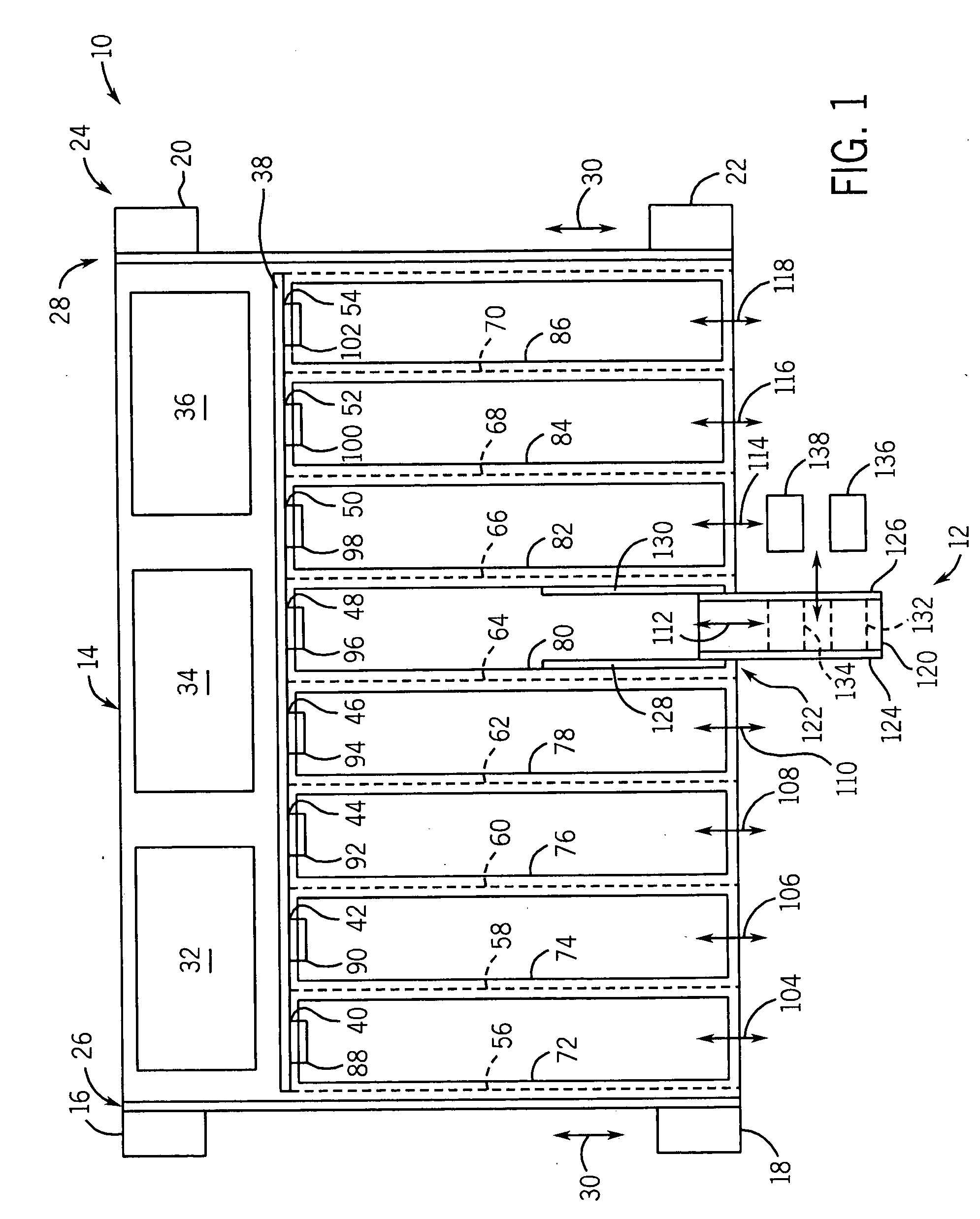
[0014]FIG. 1 is a block diagram illustrating a top view of a rack-mount computer system 10 having a hot plug fan assembly 12 in accordance with embodime...


PUM


Abstract

A fan tray for mounting in a housing to move between a retracted position within the housing and an extended position at which the fan tray extends from the front of the housing. The fan tray may comprise a flow passage having fan receptacles adapted to support removable fans such that the fans are operable to provide continuous airflow through the flow passage. In one embodiment, the housing may be provided by a blade server through which the fans direct air for cooling purposes.

Description

BACKGROUND OF THE RELATED ART [0001] This section is intended to introduce the reader to various aspects of art, which may be related to various aspects of the present invention that are described and / or claimed below. This discussion is believed to be helpful in providing the reader with background information to facilitate a better understanding of the various aspects of the present invention. Accordingly, it should be understood that these statements are to be read in this light, and not as admissions of prior art. [0002] In the computer industry, a rack-mount computer system often has a plurality of rack-mount components, such as servers, which are configured to facilitate reliable and continuous operation. In certain systems, these rack-mount components have redundant devices, such as multiple power supplies and fans. If one of these components fails or malfunctions, then the redundant component continues operations of the system until a service technician can subsequently repl...

Claims


Application Information

Patent Timeline
Patent Type & Authority Applications(United States)
IPC IPC(8): H05K5/00H05K7/20
CPCH05K7/20581
Inventor GRADY, JOHN R.BASINGER, RAY G.
Owner HEWLETT-PACKARD ENTERPRISE DEV LP
Why Eureka
Try Eureka