Beamforming method for an SDM/MIMO system

a beamforming method and beam technology, applied in diversity/multi-antenna systems, web handling, transportation and packaging, etc., can solve the problems of serious deterioration of system performance, errors in channel estimation, and difficult implementation of accurate channel estimation, so as to mitigate the degradation of sdm performance

Inactive Publication Date: 2005-11-17
SAMSUNG ELECTRONICS CO LTD +1
View PDF3 Cites 82 Cited by
  • Summary
  • Abstract
  • Description
  • Claims
  • Application Information

AI Technical Summary

Benefits of technology

[0012] Therefore, the present invention has been designed to substantially solve at least the above problems and/or disadvantages and to provide at least the advantages described belo

Problems solved by technology

In a real communication environment, however, accurate channel estimation is hard to implement and some errors are involved in the channel estimate as a result of the effects of noise and the difference in gain and phase between multiple antennas.
It is a distinctive shortcoming of SDM that because the beamforming weight is determined from the estimated channel and interference is cancelled between mobile terminals using the beamforming weight, the channel estimation error causes a serious deterioration of system performance.
That is, a beam cannot be formed in an accurate direct

Method used


Image

  • Beamforming method for an SDM/MIMO system
  • Beamforming method for an SDM/MIMO system
  • Beamforming method for an SDM/MIMO system

Examples


Embodiment Construction

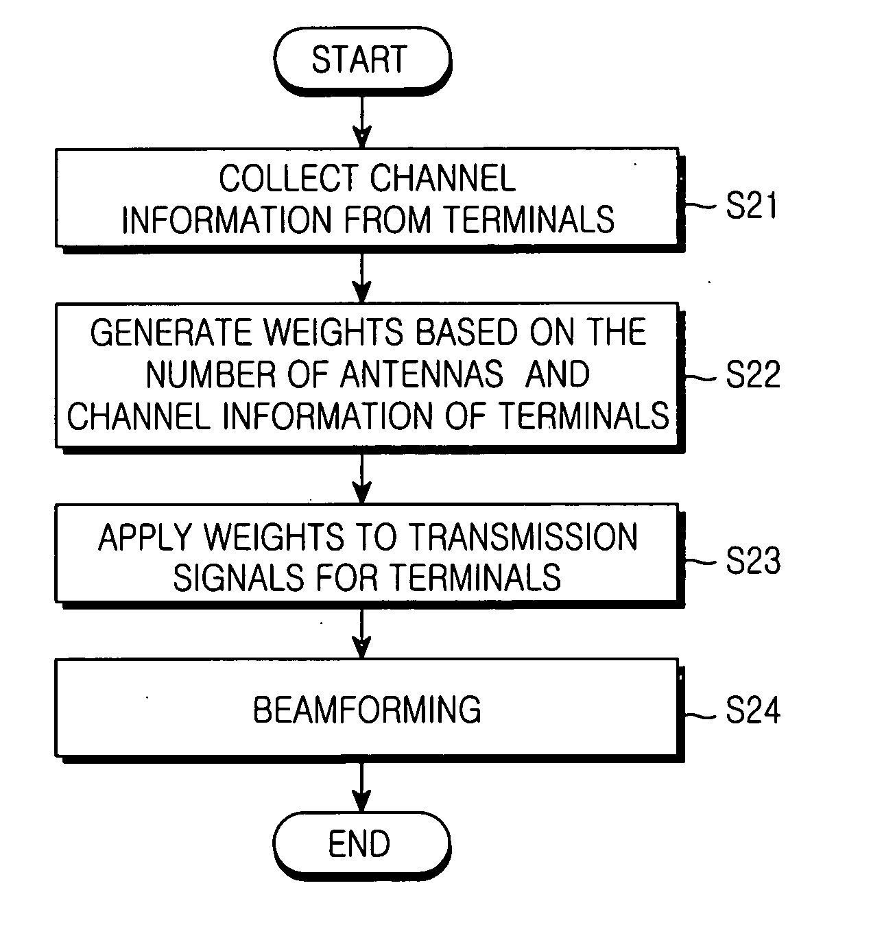
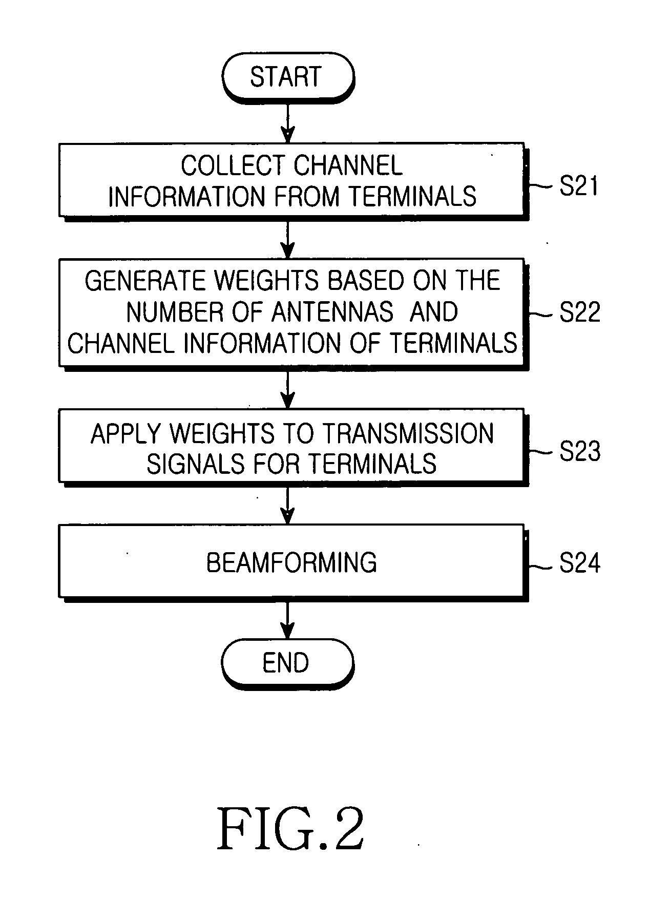
[0023] Preferred embodiments of the present invention will be described in detail herein below with reference to the accompanying drawings. In the following description, well-known functions or constructions are not described in detail since they would obscure the invention in unnecessary detail.

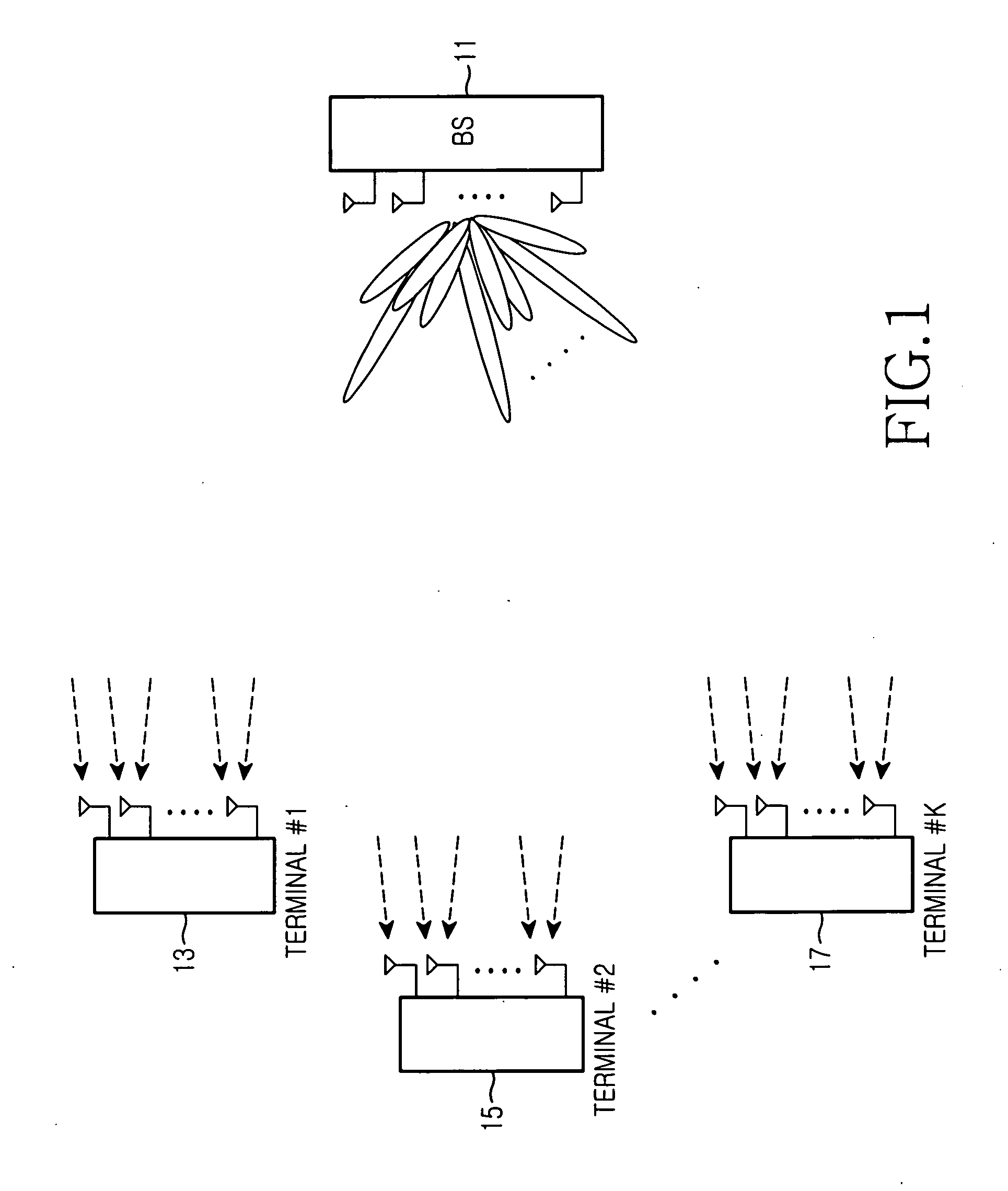
[0024]FIG. 1 illustrates an SDM / MIMO system to implement a beamforming method according to an embodiment of the present invention. Referring to FIG. 1, a BS 11 transmits signals to a plurality of mobile terminals 13, 15, and 17 through a plurality of transmit (Tx) antennas. Each of the mobile terminals 13, 15, and 17 are equipped with a plurality of receive (Rx) antennas for receiving the signals in the spatial dimension.

[0025] According to a preferred embodiment of the present invention, a communication system comprising K mobile terminals sharing one channel, N antennas at a BS, and Nr,k antennas at a kth mobile terminal (i.e. user) is illustrated. Hk is an Nr,kxNt matrix representing th...


PUM

PropertyMeasurementUnit
Weightaaaaaaaaaa
Poweraaaaaaaaaa

Abstract

A beamforming method in a communication system having a transmitter for transmitting signals to users on a plurality of transmit antennas, and spatially identifying the users and a plurality of receivers for receiving the signals discriminately. A beamforming weight is determined based on channel information received from each of the receivers, based on whether the each receiver uses a single antenna or a plurality of antennas. A transmission signal is multiplied by the beamforming weight and transmitted.

Description

PRIORITY [0001] This application claims priority under 35 U.S.C. § 119 to an application entitled “Beamforming Method for an SDM / MIMO System” filed in the Korean Intellectual Property Office on May 17, 2004 and assigned Serial No. 2004-34804, the contents of which are incorporated herein by reference. BACKGROUND OF THE INVENTION [0002] 1. Field of the Invention [0003] The present invention relates generally to an SDM / MIMO (Space Division Multiplexing / Multiple Input Multiple Output) system, and in particular, to a beamforming method for the SDM / MIMO system. [0004] 2. Description of the Related Art [0005] SDM is a scheme for transmitting signals from a base station (BS) to mobile terminals on multiple antennas, while spatially identifying them. This scheme forms a beam for each mobile terminal and cancels interference between mobile terminals, such that a plurality of mobile terminals share one channel without interference. Advantageously, the capacity of a system sharing one channel ...

Claims


Application Information

Patent Timeline
IPC IPC(8): H04B7/04H04B7/06
CPCH04B7/0626H04B7/0617B65H18/04B65H75/243B65H2301/4136
Inventor LEE, KYUNG-CHUNCHUN, JOO-HWANCHUNG, JAE-HAKNAM, SEUNG-HOON
Owner SAMSUNG ELECTRONICS CO LTD
Why Eureka
Try Eureka