Automatic cutting method for digital images
a cutting method and digital image technology, applied in the field of digital image processing methods, can solve the problem of hard to accurately determine the boundary of the image using the normal method, and achieve the effect of reducing the interference of speckles, precise positioning, and faster processing speed
- Summary
- Abstract
- Description
- Claims
- Application Information
AI Technical Summary
Benefits of technology
Problems solved by technology
Method used
Image
Examples
first embodiment
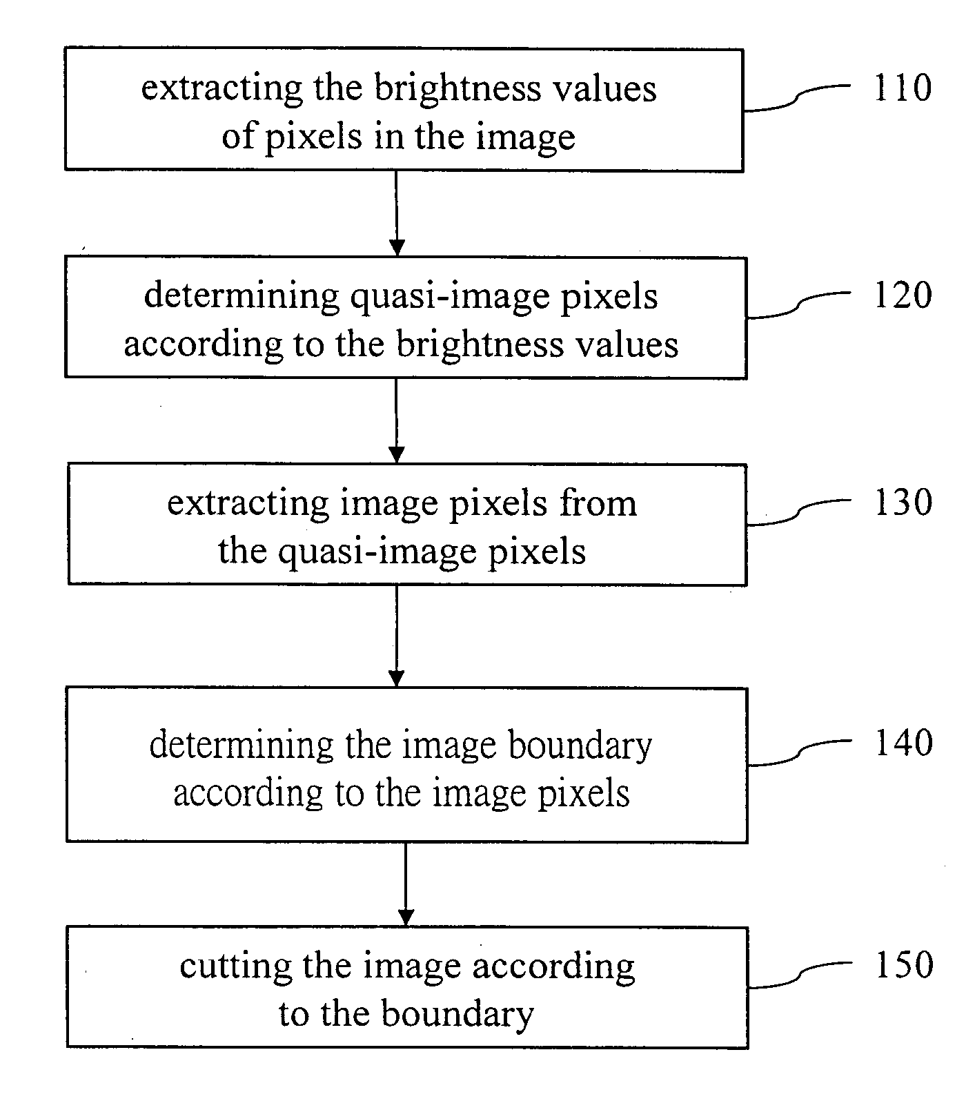
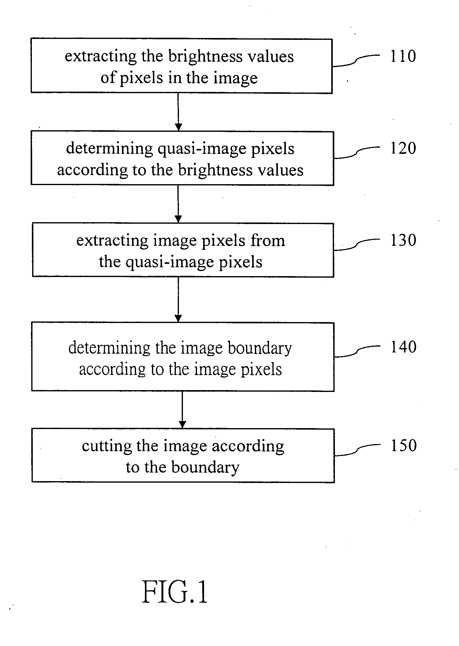
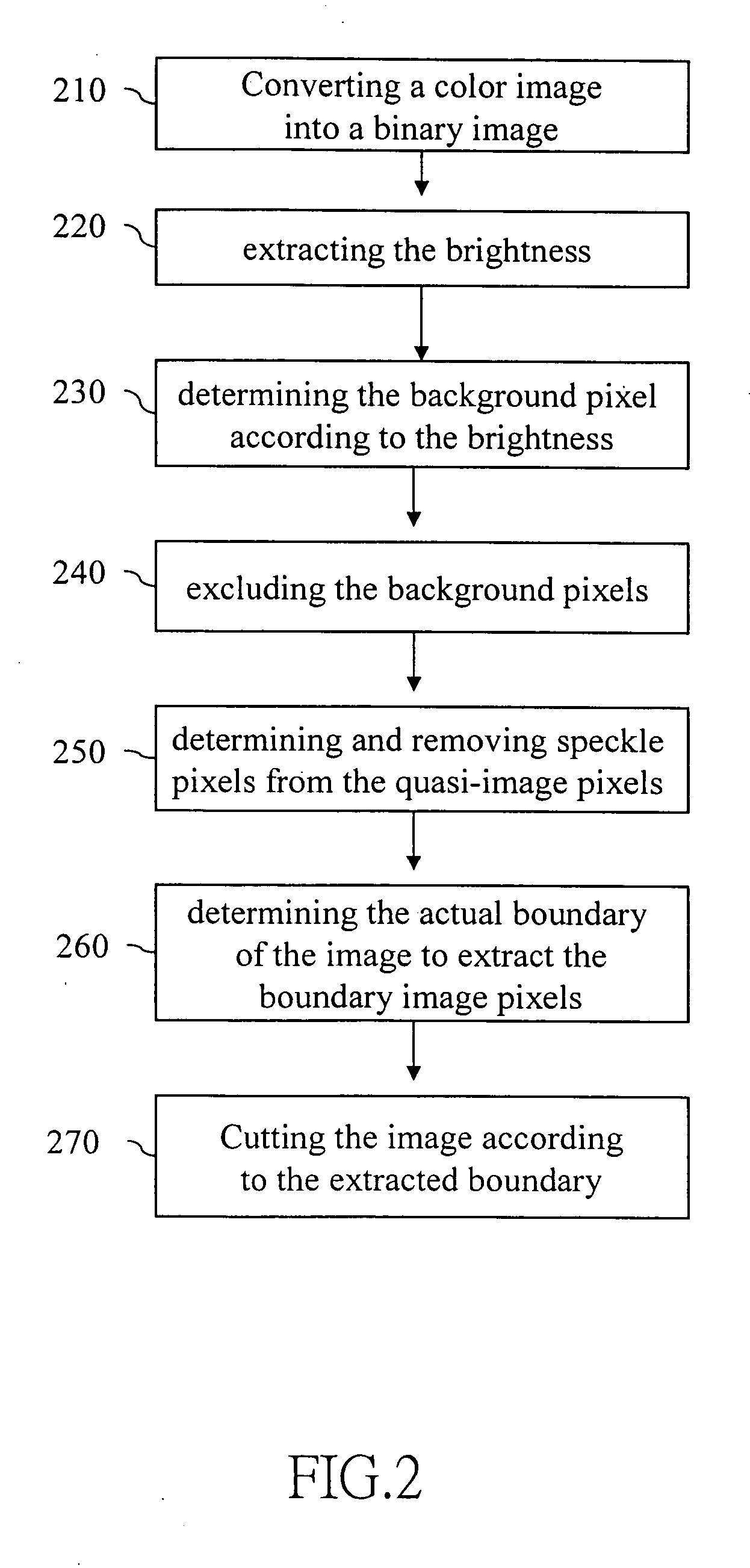
[0021]FIG. 2 shows the flowchart of the invention. First, an image is read into the system. If the image is a color image, it is converted into a binary image (step 210). The image is then converted into the YcbCr format. Each pixel in the image is processed, extracting the brightness, Y (step 220). The Y value is compared with a first base value. The first base value is also called bi-level threshold, and it can be got by taking the average value of two wave crest of an image's grayscale histogram. In the current embodiment, the first base value is 150. If Y is greater than 150, it is considered as a background pixel (step 230). The pixels in the image include background pixels and quasi-image pixels. The quasi-image pixels further include speckle pixels and actual image pixels. After excluding the background pixels (step 240), the image is left with quasi-image pixels. Speckle pixels are further determined and removed from the quasi-image pixels (step 250). Finally, we are left wi...
third embodiment
[0025] Please refer to FIG. 6 for determining the image boundary according to the invention. First, the image is converted into the YcbCr format. The pixels in the image are scanned from outside toward inside in all four directions (step 610). The scanning from top and bottom is by rows, while the scanning from left and right is by columns. The background pixels and speckle pixels in the image are removed. The rows of the first pixels found by scanning from top and bottom are marked as the boundary of the image. Likewise, the columns of the first pixels found by scanning from left and right are also marked as the boundary of the image (step 620). The image is then cut according to the boundary (step 630). The current embodiment scans the image from the boundary toward the center until image points are found. Therefore, it does not need to scan all points in the image and saves a lot of time.
fourth embodiment
[0026]FIG. 7 shows the procedure of determining the image boundary according to the invention. This embodiment uses the upper left pixel and the lower right pixel of the image to determine the image boundary. The procedure starts from the top of the image and scans from left to right. The first encountered image pixel is marked as the upper left pixel (step 710). Afterwards, the scanning starts from the bottom of the image and from right to left. The first encountered pixel is marked as the lower right pixel (step 720). After determining the upper left pixel and the lower right pixel of the actual image, the image boundary is determined from the two pixels (step 730). The image is then cut according to the boundary.
PUM
 Abstract
Description
Claims
Application Information
 - R&D
- Intellectual Property
- Life Sciences
- Materials
- Tech Scout
- Unparalleled Data Quality
- Higher Quality Content
- 60% Fewer Hallucinations
Browse by: Latest US Patents, China's latest patents, Technical Efficacy Thesaurus, Application Domain, Technology Topic, Popular Technical Reports.
© 2025 PatSnap. All rights reserved.Legal|Privacy policy|Modern Slavery Act Transparency Statement|Sitemap|About US| Contact US: help@patsnap.com


