Wound closure material applicator

a wound closure and material technology, applied in the field of applications, can solve problems such as undesirable drippage, and achieve the effect of reducing the drippage of wound closure materials

Inactive Publication Date: 2005-11-17
TYCO HEALTHCARE GRP LP
View PDF40 Cites 14 Cited by
  • Summary
  • Abstract
  • Description
  • Claims
  • Application Information

AI Technical Summary

Benefits of technology

[0006] In accordance with one preferred embodiment of the present disclosure, a wound closure material applicator is provided which includes a handle assembly having a movable handle or trigger and a stationary handle. A body portion extends distally from the handle assembly and defines a body channel dimensioned to receive wound closure material or a reservoir of wound closure material. A tip assembly is supported adjacent the distal end of the body portion and includes a seal member, a valve seat and a discharge channel positioned distally of the valve seal The seal member is movable distally within the tip assembly from a closed position in which the seal member engages the valve seat to an open position in which the seal member is spaced from the valve seat. The tip assembly is configured such that movement of the seal member from the open position to the closed position causes a reduction of pressure within the discharge channel of the tip assembly to minimize drippage of wound closure material from the applicator. Preferably, the seal member is urged toward the closed position by a biasing member.

Problems solved by technology

Due to the location of use of wound closure material applicators, e.g., body cavities, body tissue, etc., such drippage is undesirable.

Method used


Image

  • Wound closure material applicator
  • Wound closure material applicator
  • Wound closure material applicator

Examples


Embodiment Construction

[0060] Preferred embodiments of the presently disclosed wound closure material applicator will now be described in detail with reference to the drawings, wherein like reference numerals designate identical or corresponding elements in each of the several views:

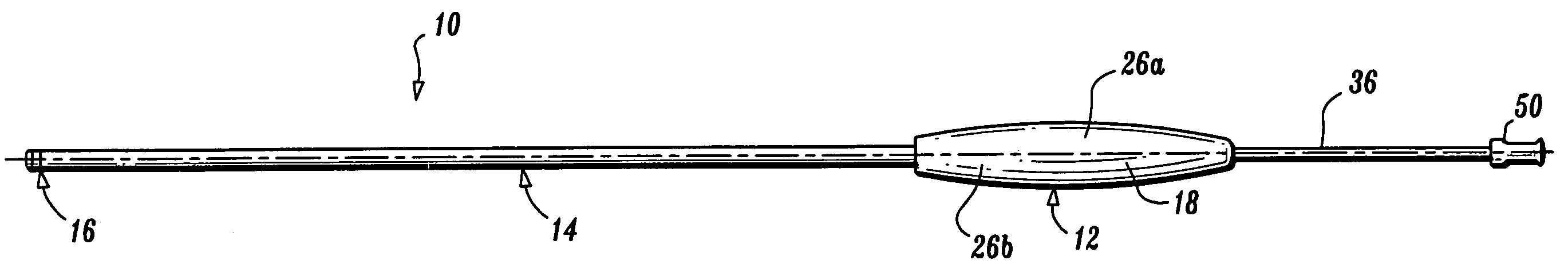
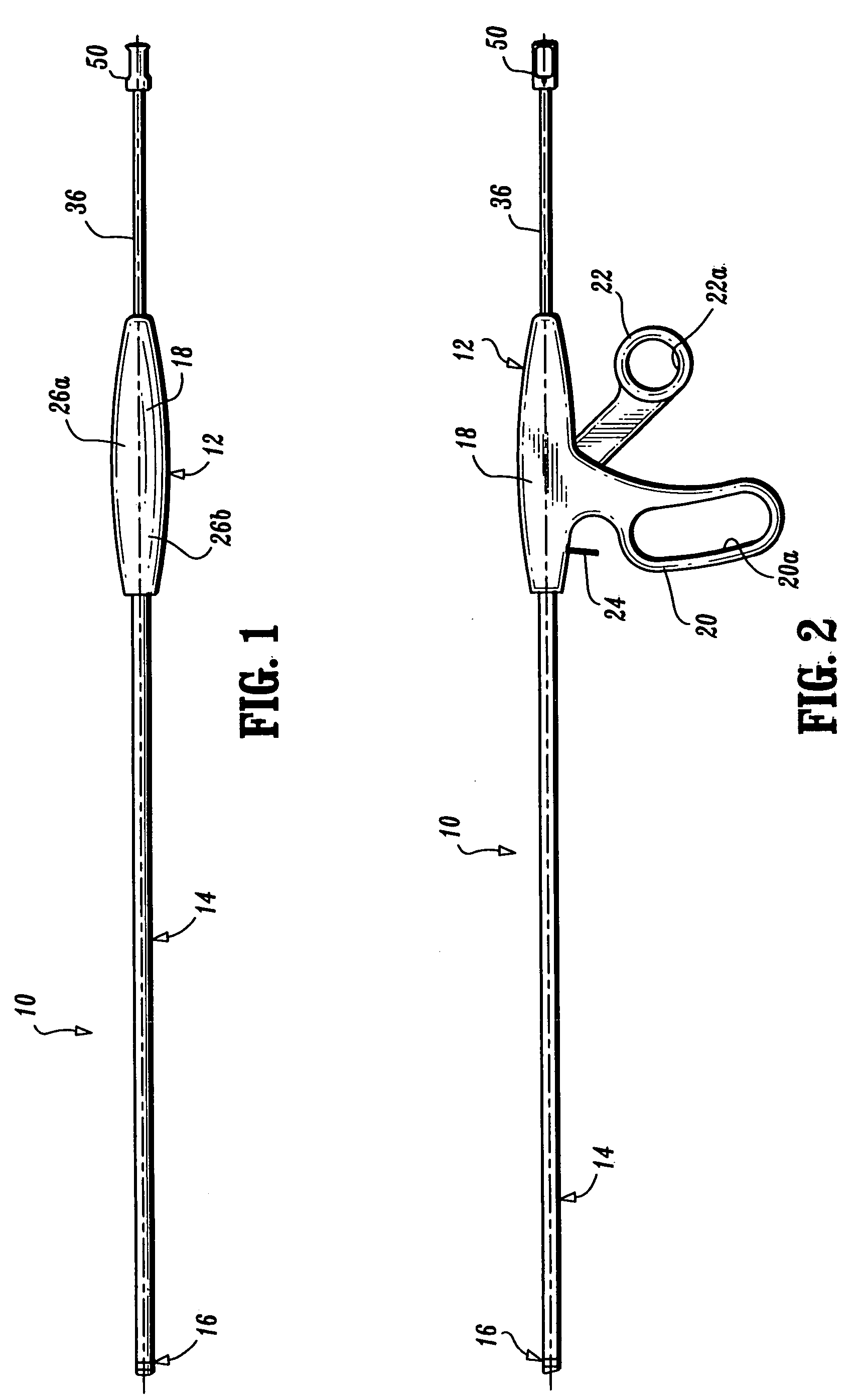
[0061]FIGS. 1 and 2 illustrate one embodiment of the presently disclosed wound closure material applicator shown generally as 10. Wound closure material applicator 10 includes a handle assembly 12, an elongated body portion 14 and a distally positioned tip assembly 16. Handle assembly 12 includes a barrel portion 18, a stationary handle portion 20, a movable handle portion or trigger 22 and a locking member 24. Handle portions 20 and 22 include finger loops 20a and 22a, respectively, which facilitate gripping of the instrument. Body portion 14 has a proximal end secured to handle assembly 14 and a distal end supporting tip assembly 16.

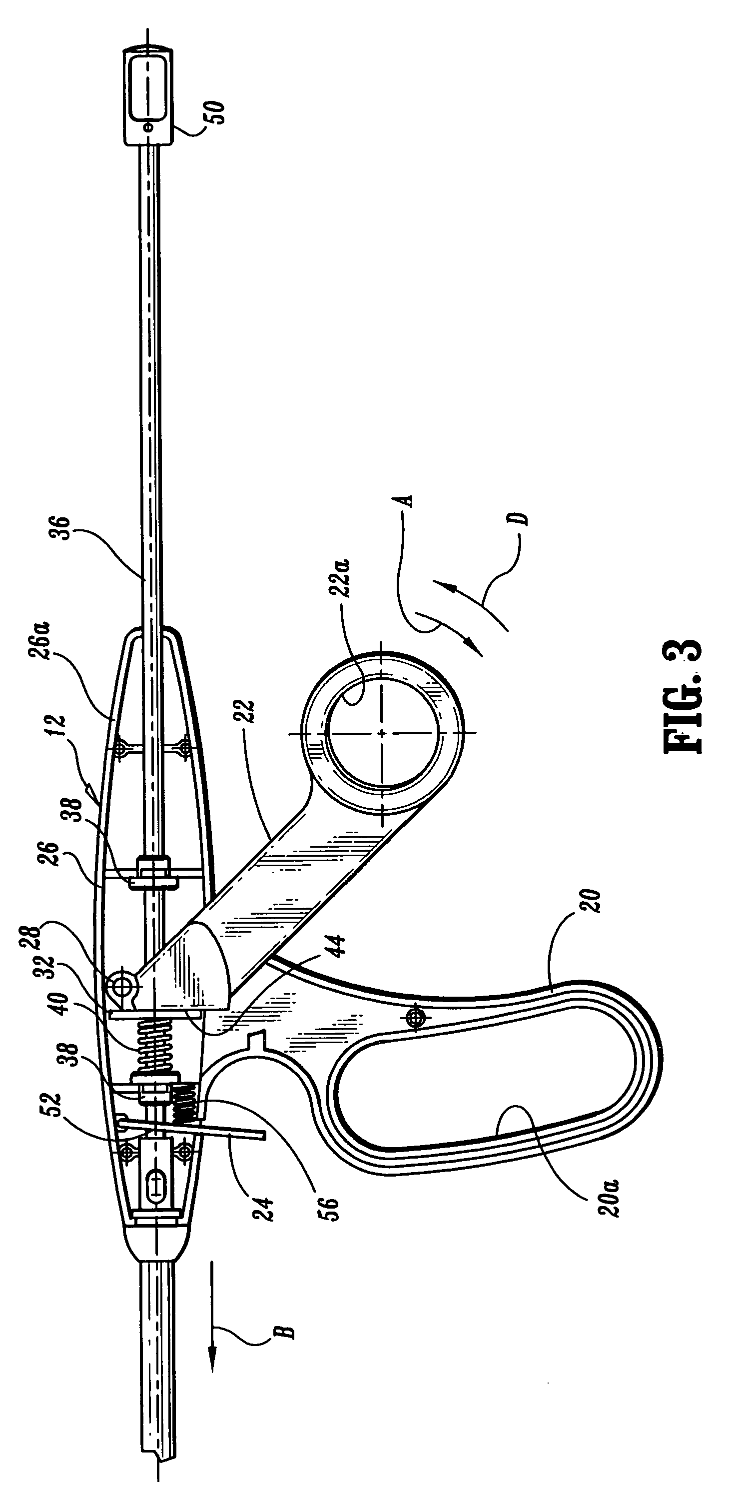
[0062] Referring to FIG. 3, handle assembly 12 includes a body 26 formed from body half-sec...


PUM

PropertyMeasurementUnit
angleaaaaaaaaaa
angleaaaaaaaaaa
angleaaaaaaaaaa

Abstract

A wound closure material applicator is provided which includes a handle assembly having a movable handle, a body portion extending distally from the handle assembly and a tip assembly supported adjacent the distal end of the body portion. The tip assembly includes a housing defining a bore, a tip member and a seal member. The tip assembly housing defines an inlet channel and a valve seat positioned adjacent the outlet of the inlet channel. The seal member is movable distally within the housing bore from a closed position in which the valve member abuts the valve seat to an open position in which the valve member is spaced from the valve seat. The tip assembly is configured such that movement of the seal member from the open to the closed position causes a reduction of pressure within a discharge channel of the tip assembly to minimize drippage of wound closure material from the applicator.

Description

BACKGROUND [0001] 1. Technical Field [0002] The present disclosure relates to an applicator for applying a fluid material onto a surface. More specifically, the present disclosure relates to an applicator for applying a wound closure material onto tissue for wound repair. [0003] 2. Background of Related Art [0004] Applicators for applying wound closure materials, for example, adhesives, sealants and hemostats, to tissue to effect wound repair are well known in the art. Typically, such applicators include a tube or syringe and a plunger or driver which is advanceable through the syringe to force the wound closure material from the syringe. Such a device is disclosed in U.S. Pat. No. 6,027,471. In such devices, the distal end of the syringe is open and the wound closure material is retained within the syringe by surface adhesion of the wound closure material to the internal walls of the syringe. After the wound closure material is dispensed from the syringe, drippage of the wound clos...

Claims


Application Information

Patent Timeline
Patent Type & Authority Applications(United States)
IPC IPC(8): A61B17/00A61L24/00A61M31/00A61M35/00A61M37/00B05C17/005B05C17/01
CPCA61B17/00491A61M35/003B05C17/014B05C17/01B05C17/00583
Inventor CRISCUOLO, CHRISTOPHER J.ARANYI, ERNIE
Owner TYCO HEALTHCARE GRP LP
Why Eureka
Try Eureka