
Artificial disc device

a technology of discs and discs, applied in the field of artificial disc devices, can solve the problems of end plates prone to subsidence or fall around the ball, require more complex shapes, so as to reduce stress and wear that would otherwise occur in either of the interfaces, take up compressive loading, and reduce the effect of stress and wear

Inactive Publication Date: 2005-11-17
PIONEER SURGICAL TECH INC
View PDF66 Cites 23 Cited by
  • Summary
  • Abstract
  • Description
  • Claims
  • Application Information

AI Technical Summary

Benefits of technology

"The present invention provides an artificial disc device that includes a central bearing portion and an outer bearing portion that move relative to each other. The central bearing portion has upper and lower surfaces that can shift with the vertebral movement. The outer bearing portion has inner surfaces that can move relative to the vertebral surfaces. The device is designed to allow for movement between the vertebral surfaces and to distribute the load across the device to minimize localized forces on the vertebral surfaces. The device can be made with a hard metallic material or a hard plastic material for load bearing purposes. The outer bearing portion can be filled with elastic material or have a hollow core for shock absorption. The device can be bi-polar, with two interfaces that shift with respect to each other, reducing stress and wear. The device can be lubricated and sealed to prevent leakage while still allowing for low friction sliding."

Problems solved by technology

However, devices such as these usually require special surface materials and / or surface treatments that allow for bone ingrowth for fixing the members to the vertebrae.
Moreover, these devices have had problems with migration where the intermediate bearing body shifts out from between the vertebrae, and thus generally require more complex shapes to form stops for resisting such disc shifting.
The ball approach, while effective to provide a good range of motion, tended to create subsidence problems.
In other words, since these ball implants were not of a size that enabled the load of the spine to be distributed evenly thereacross, the end plates tended to subside or fall around the ball.
However, these approaches are limited in their use to patients who have a substantially undamaged disc annulus.

Method used


Image

  • Artificial disc device
  • Artificial disc device
  • Artificial disc device

Examples


Embodiment Construction

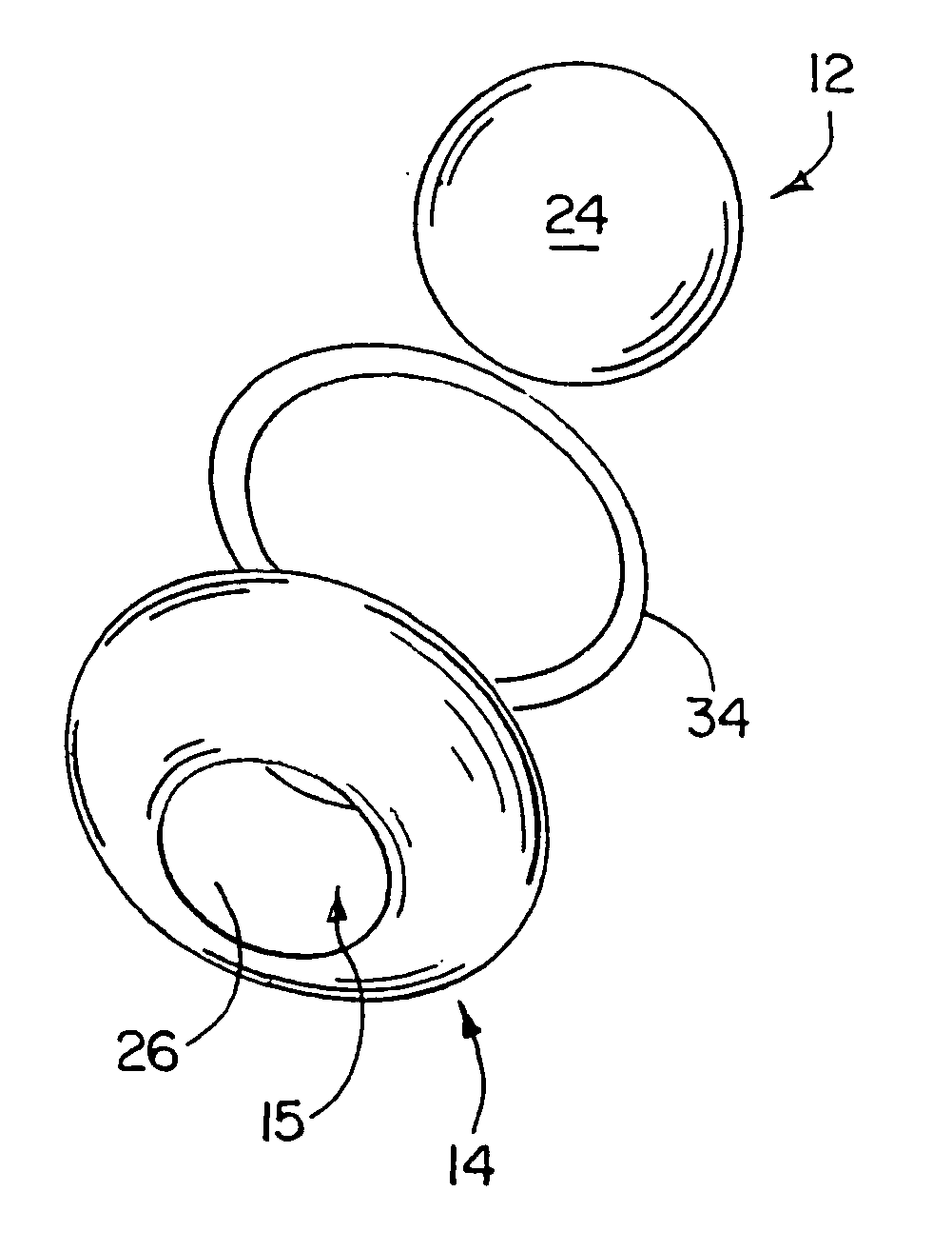
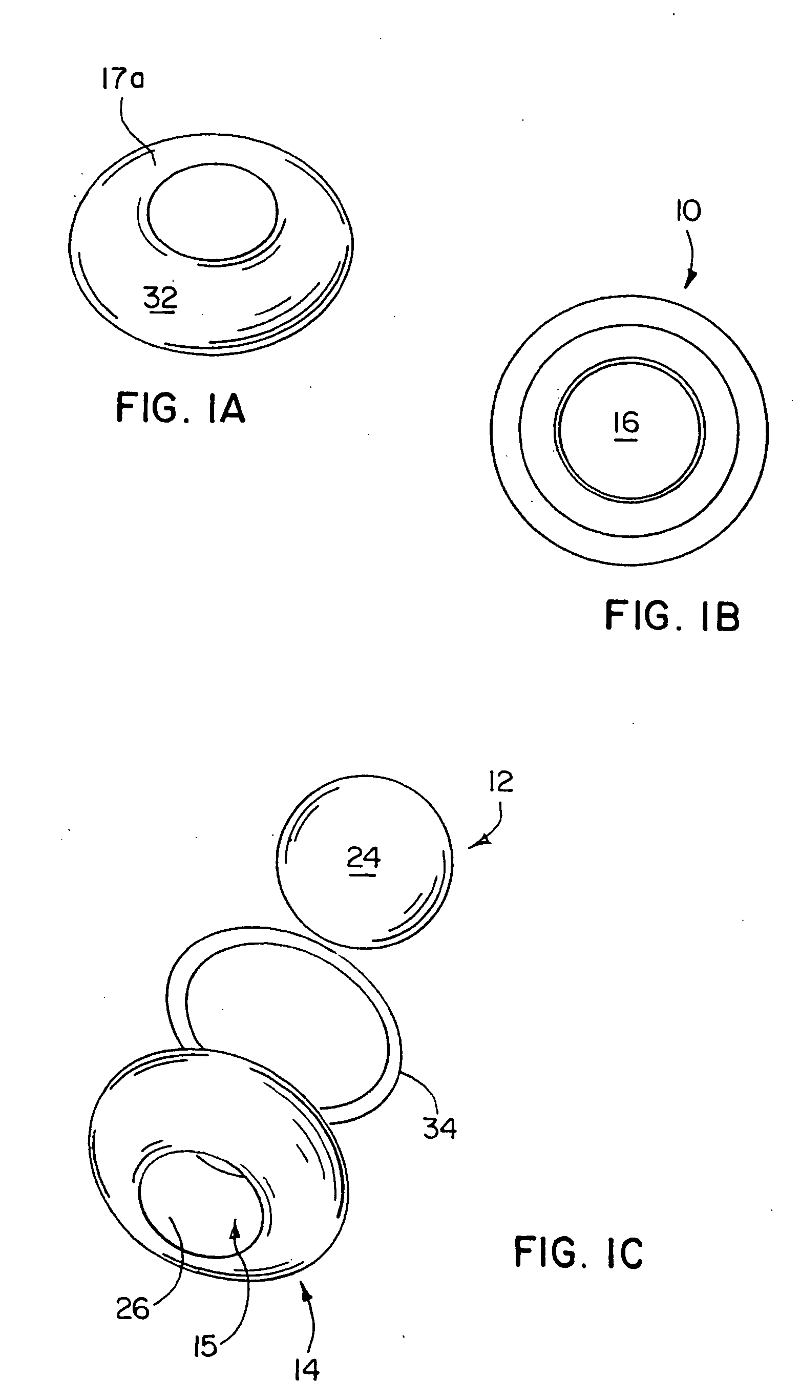
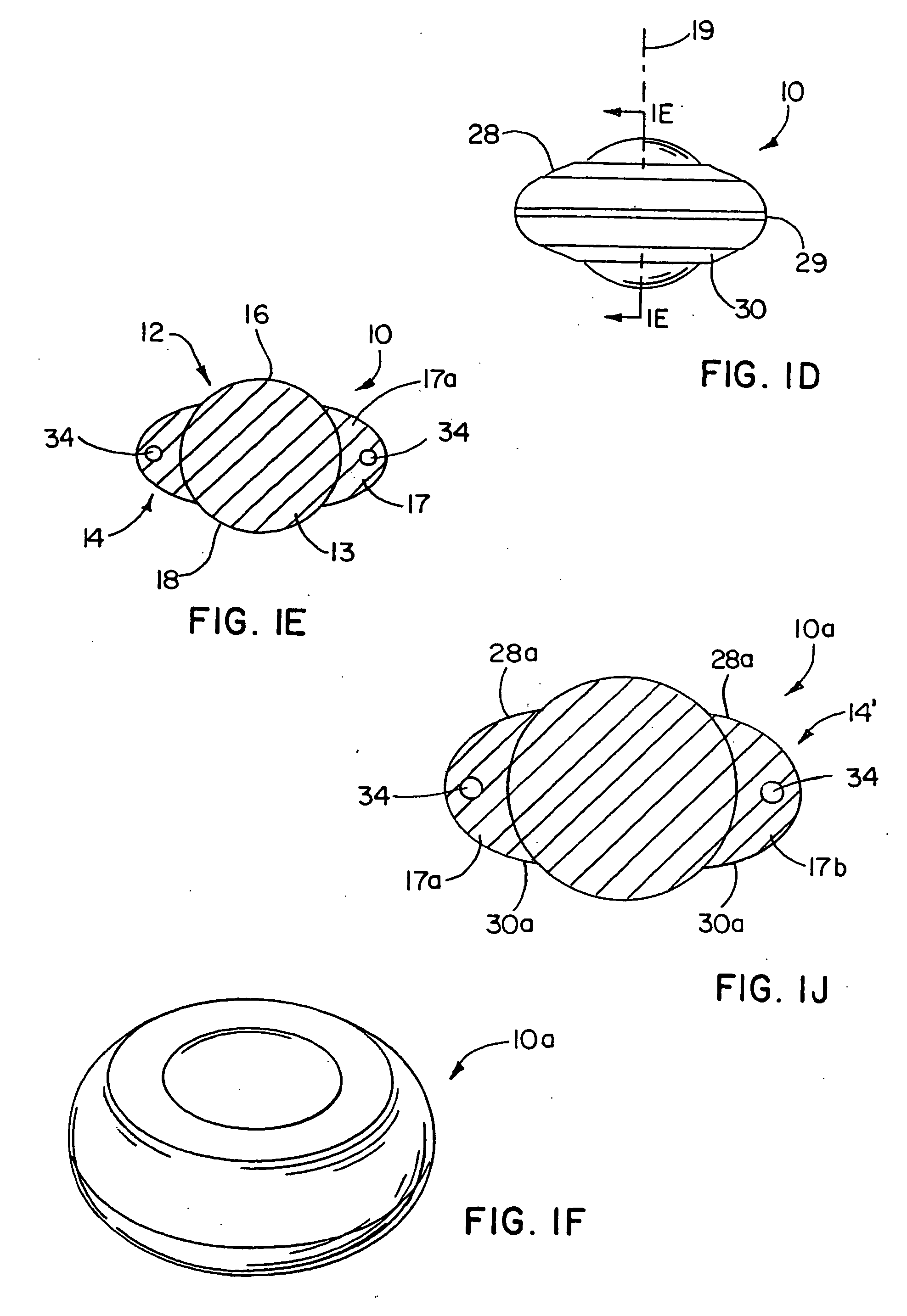
[0028] Referencing FIGS. 1A-1E, an artificial disc device 10 is shown which includes an enlarged, central bearing portion 12, and a substantially annular, outer bearing portion 14 having a through opening 15 in which the central bearing portion 12 is disposed. Herein, preferred shapes, configurations and material selections for the inner and outer bearing portions are set forth. However, in each case, these selections are not meant to be limiting as other selections that serve the purpose of the disc implant described herein are also contemplated. Likewise, several embodiments are disclosed that have structural features that can be implemented substantially interchangeably among the disc implants.

[0029] In the form illustrated in FIGS. 1A-1E, the central bearing 12 has an axially enlarged body 13 relative to the outer bearing 14 so that it generally includes arcuate surface portions 16 and 18 that project above and below the radially outer bearing portion 14 for engaging in indents...


PUM

PropertyMeasurementUnit
thicknessaaaaaaaaaa
thicknessaaaaaaaaaa
distanceaaaaaaaaaa

Abstract

Artificial disc devices are disclosed that restore correct anatomical intervertebral spacing for damaged discs while maintaining a substantially normal range of biomechanical movement for the vertebrae between which they are implanted. The disc devices include center bearing and outer or annular bearing portions with the center bearing portion including generally axially extending locating surfaces which cooperate with the facing vertebral surfaces to resist migration. The outer bearing portion is for load bearing or load sharing with the center bearing portion and includes surfaces that extend radially toward the periphery of the vertebrae so that subsidence about the center bearing portion is minimized. Alternate forms of the disc devices include one with an axially enlarged center ball bearing having an annular ring bearing extending thereabout and another having upper and lower plate members with a central bumper member and a surrounding resilient annular member therebetween.

Description

CROSS-REFERENCE TO RELATED APPLICATION [0001] This application is a continuation of U.S. patent application Ser. No. 10 / 282,620, filed Oct. 29, 2002, entitled “Artificial Disc Device,” which claims priority to U.S. Provisional Application No. 60 / 382,758, filed May 23, 2002, entitled “Artificial Intervertebral Disc Device,” and which are incorporated by reference herein in its entirety.BACKGROUND OF THE INVENTION [0002] Artificial disc technology has been employed to correct damaged spinal discs for relieving back pain and restoring or maintaining intervertebral spacing while attempting to minimize their constraining effects on the normal biomechanical movement of the spine. Two types of artificial discs have generally been employed: the artificial total disc which is designed to substitute for the entire disc, i.e. the annulus, nucleus and possibly the end plates as well; and the artificial nucleus where only the nucleus is replaced with the annulus and end plates remaining intact. ...

Claims


Application Information

Patent Timeline
Patent Type & Authority Applications(United States)
IPC IPC(8): A61F2/00A61F2/30A61F2/44
CPCA61F2/30742Y10S606/907A61F2/442A61F2/4425A61F2002/30014A61F2002/30016A61F2002/30123A61F2002/302A61F2002/30242A61F2002/30245A61F2002/30299A61F2002/30311A61F2002/30331A61F2002/3039A61F2002/305A61F2002/30528A61F2002/30563A61F2002/30581A61F2002/30649A61F2002/30673A61F2002/30685A61F2002/30738A61F2002/30784A61F2002/30841A61F2002/30919A61F2002/30934A61F2002/30935A61F2002/443A61F2002/444A61F2220/0025A61F2220/0033A61F2230/0006A61F2230/0065A61F2230/0071A61F2230/0093A61F2250/0018A61F2250/0019A61F2310/00017A61F2310/00023A61F2310/00179A61F2310/00574A61F2/30965
Inventor SONGER, MATTHEW N.KILPELA, THOMAS S.JANOWSKI, BRIAN P.BERREVOETS, GREGORY A.GEPHART, MATTHEW P.
Owner PIONEER SURGICAL TECH INC
Learn More