
Lightweight concrete composite blocks

a composite block and lightweight technology, applied in the direction of moulds, mould fastening means, building components, etc., can solve the problems of concrete being expensive, wood is unfortunately extremely expensive, and often does not provide the structural safety available from other building materials

Inactive Publication Date: 2005-11-24
AMAZON FORMS ONE
View PDF6 Cites 14 Cited by
  • Summary
  • Abstract
  • Description
  • Claims
  • Application Information

AI Technical Summary

Benefits of technology

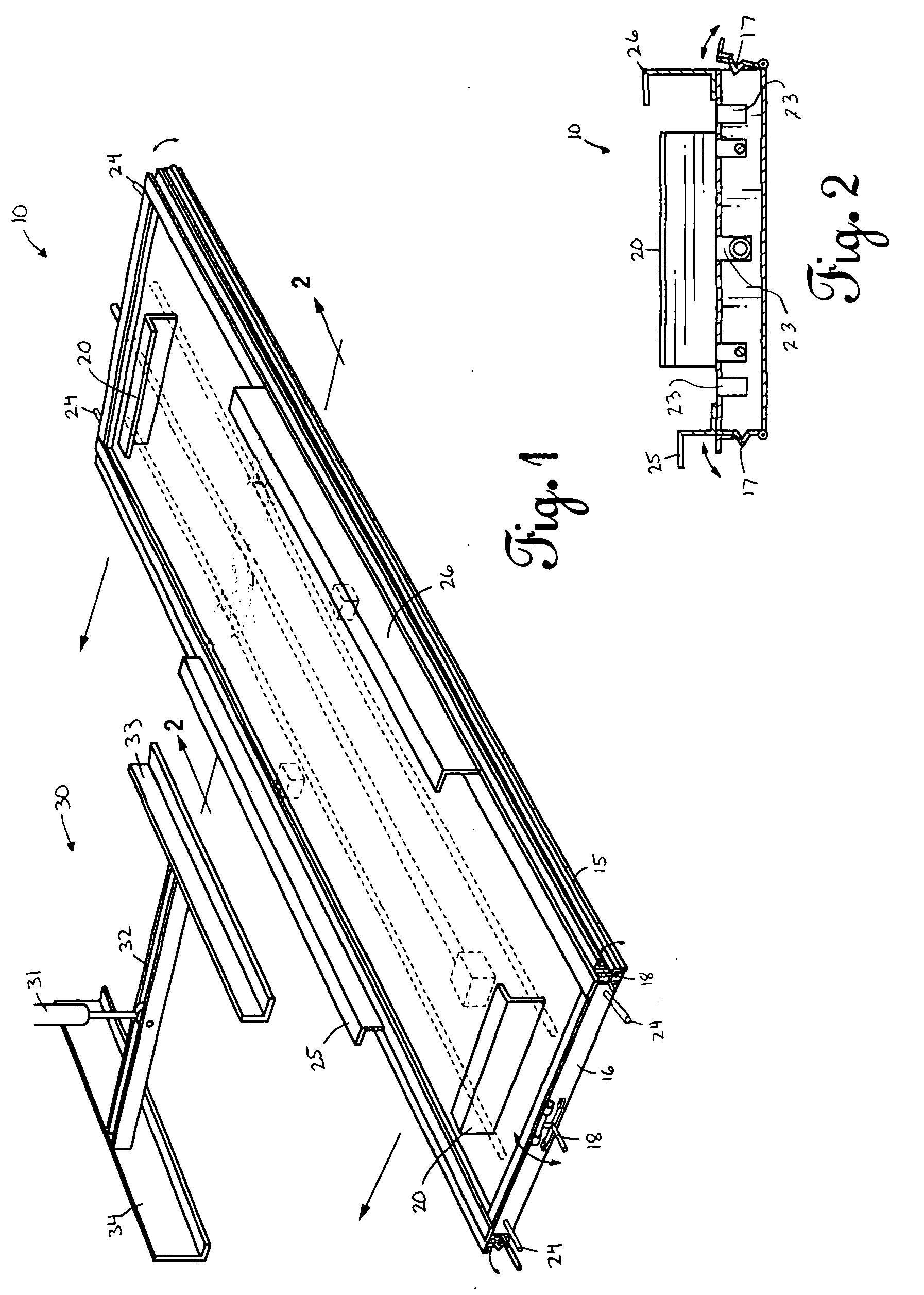
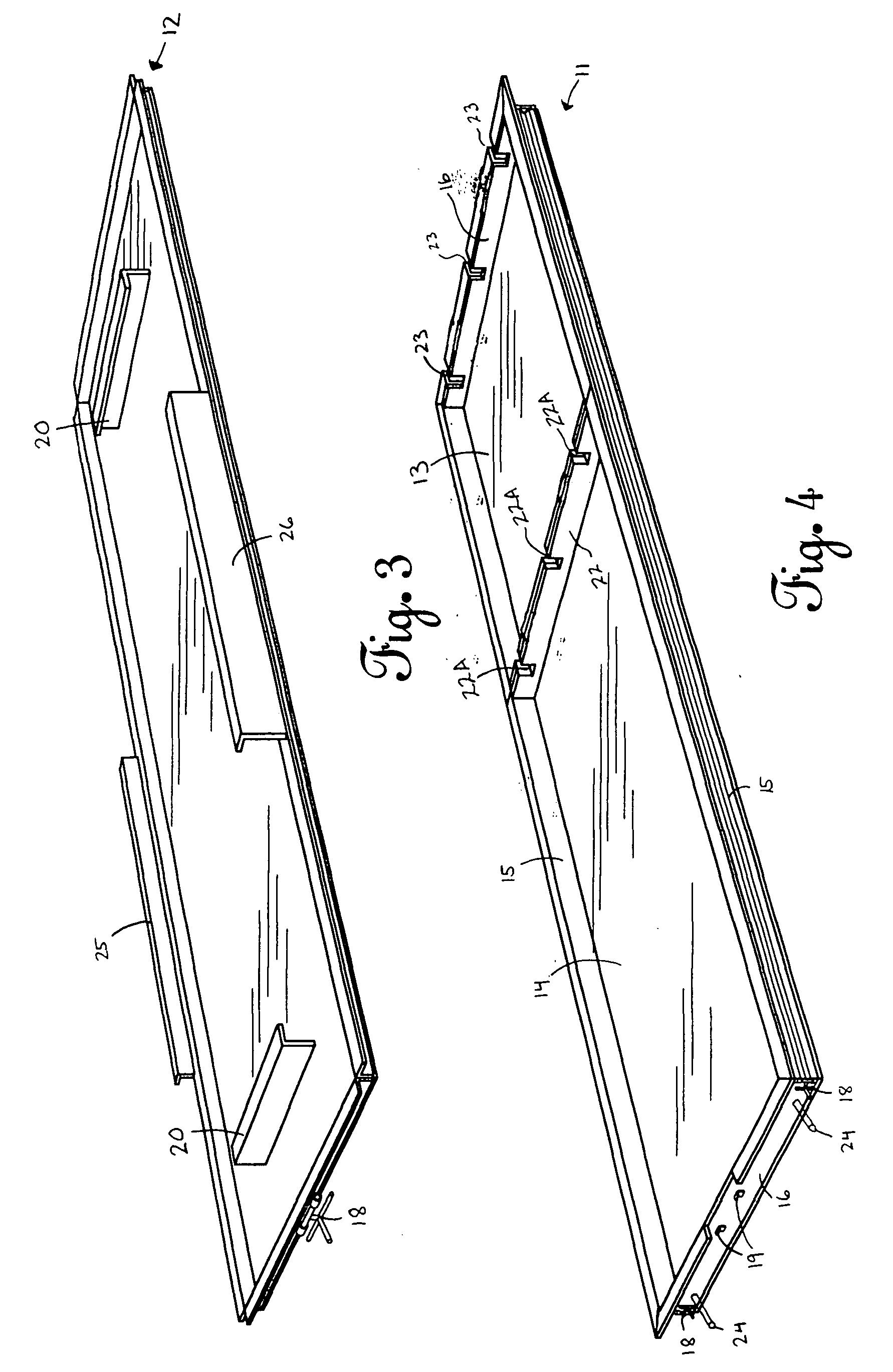
[0009] An apparatus for manufacturing lightweight concrete composite blocks includes a form, a form loading station, a form assembly station, a station conveyor, a curing oven, and a block removal station. The form defines a desired shape that holds a volume of composite. The form loading station receives composite and delivers the composite to the form. The form assembly station facilitates assembly of the form. The station conveyor conveys the form about the apparatus in a continuous loop. The curing oven cures the composite into a lightweight concrete composite block. The block removal station removes the lightweight concrete composite block from the form.
[0016] It is therefore an object of the present invention to provide lightweight concrete composite blocks suitable in building walls.
[0018] It is a further object of the present invention to provide a method of using lightweight concrete composite blocks in constructing a structure.

Problems solved by technology

Wood unfortunately has become extremely expensive due to reduced supplies caused by restrictions resulting from today's environmentally conscious society.
Further, wood often does not provide the structural safety available from other building materials, such as concrete.
Concrete is unfortunately expensive, which restricts its use to projects requiring the structural safety advantages associated with concrete.
Unfortunately, the reduced materials costs of lightweight concrete are counteracted through manufacturing difficulties, which drive up costs.
Furthermore, there does not currently exist lightweight concrete blocks suitable for use in constructing interior walls.

Method used


Image

  • Lightweight concrete composite blocks
  • Lightweight concrete composite blocks
  • Lightweight concrete composite blocks

Examples


Embodiment Construction

[0034] As illustrated in FIG. 11, the preferred embodiment of the block 10A discloses a rectangular block with a top end, a bottom end, and two sides. One side defines a raised tongue 106 while the opposite side defines a recessed groove 107, whereby blocks can be assembled in a successive fashion by fitting a tongue side into a groove side. In addition, the block 10A includes electrical conduit 200 and electrical boxes 201 for running electrical wire and making electrical connections. While the preferred embodiment discloses electrical conduit 200 and electrical boxes 201, those of ordinary skill in the art will recognize that any multitude of items normally used inside building walls may be substituted, such as plumbing piping, air ducts, and the like. The ability of the block 10A to contain electrical conduit and electrical boxes makes it ideal for use as an interior wall in buildings.

[0035] As illustrated in FIG. 10, an apparatus 1 for manufacturing unitary lightweight concrete...


PUM

PropertyMeasurementUnit
Depthaaaaaaaaaa

Abstract

An apparatus for manufacturing lightweight concrete composite blocks includes a form, a station conveyor, a form-loading station, a form assembly station, a curing oven, and a block removal station. The station conveyor conveys the form or a multitude of forms around the apparatus in a continuous loop to produce a desired rate of production of lightweight concrete composite blocks. The form-loading station fills the form with a lightweight concrete composite. The form assembly station assembles the form to seal the composite within the form. The curing oven cures the lightweight concrete composite into a lightweight concrete composite block. The block removal station removes the lightweight concrete composite block from the form prior to the return of the form to the form-loading station for re-use.

Description

CROSS-REFERENCE TO RELATED APPLICATION [0001] This application is a continuation-in-part of application Ser. No. 09 / 887,369, which was filed Jun. 22, 2001.BACKGROUND OF THE INVENTION [0002] 1. Field of the Invention [0003] The present invention relates to lightweight concrete and, more particularly, but not by way of limitation, to unitary lightweight concrete composite blocks, an apparatus and corresponding method for manufacturing unitary lightweight concrete composite blocks, and a method of using unitary lightweight concrete composite blocks. [0004] 2. Description of the Related Art [0005] The primary building materials utilized today are wood and concrete. Wood unfortunately has become extremely expensive due to reduced supplies caused by restrictions resulting from today's environmentally conscious society. Further, wood often does not provide the structural safety available from other building materials, such as concrete. Concrete is unfortunately expensive, which restricts i...

Claims


Application Information

Patent Timeline
IPC IPC(8): B28B7/00B28B15/00E04C2/52
CPCB28B7/0014B28B23/0025B28B15/00B28B7/0079
Inventor SUMRALL, ORBIN F.
Owner AMAZON FORMS ONE
Learn More