Fuel delivery pipe

a technology of fuel delivery pipe and fuel injection pump, which is applied in the direction of liquid fuel feeder, machine/engine, fuel injecting pump, etc., can solve the problems of large pressure wave, pressure pulsation, and uncomfortable feeing of drivers or passengers, and achieve the effect of reducing pressure pulsation

Active Publication Date: 2005-11-24
USUI KOKUSAI SANGYO KAISHA LTD
View PDF10 Cites 11 Cited by
  • Summary
  • Abstract
  • Description
  • Claims
  • Application Information

AI Technical Summary

Benefits of technology

[0050] (11) the cross section shape in the perpendicular direction to the axis of the fuel delivery body is the substantially rectangular shape, in which a substantially center portion of either of two long side wall surfaces is inwardly bent in a concaved shape as formed in a substantially goggles shape.
[0051] It is to be noted that each of the cross section shapes does not need to be exactly in a horizontally symmetric shape. The socket to be connected to the fuel delivery body may be arranged at any position of an upper surface, a bottom surface, and two side surfaces of the wall surface while the fuel delivery body is used in a state where the wall surface connected to the socket is exposed a lower side.
[0055] (C) a pipe in which a member partly overlapped on one another by pressing work.
[0056] With the first to tenth inventions, a plate thickness, an aspect ratio, or material or strength of constructing members of an outer wall portion and the absorbing wall surface of the fuel delivery body can be determined through experiments or analyses so that the vibration or pulsation is to be at the lowest level particularly during the period of an engine idling.
[0057] The fuel delivery pipe according to the first to tenth inventions can maintain the interchangeability with conventional fuel delivery pipes by maintaining an installation dimension of brackets.
[0058] The eleventh invention relates to a structure (mechanism) for reducing the pressure pulsation and the radiant sound, and where the pressure pulsation occurs in association with the fuel injection via the injection nozzles, value of a pressure fluctuation relates closely to sonic speed αL of fuel flowing through the interior of the fuel delivery pipe and to internal volume of the fuel delivery body, and the relation thereof is set as a proportional expression described as following Numerical Expression 1. P∝α⁢ ⁢LV[Numerical⁢ ⁢Expression⁢ ⁢1]

Problems solved by technology

Because it is undesirable that the gasoline vaporizes due to the temperature increase and has negative effects on environment, the fuel delivery pipe as the returnless type has been proposed, which does not return the surplus fuel to the fuel tank.
With this fuel delivery pipe of the returnless type, where the fuel is injected from the injection nozzle into the intake pipes or the cylinders, since there is no pipe for returning the surplus fuel to the fuel tank, pressure fluctuation of the fuel inside the fuel delivery pipe becomes large and causes large pressure waves, so that the pressure pulsation occurs greatly in comparison with the fuel delivery pipe of the return type.
Consequently, the pressure pulsation is propagated as noises in the passenger compartment via clips fastening the under floor pipe arrangement, thereby giving uncomfortable feeing to the driver or passengers.
However, the pulsation dampers and the vibration absorbing clips are expensive and increase the number of components to result in higher costs while raising a new problem on ensuring an installation space.
The above described conventional arts, however, have the absorption effects for the pressure pulsation but raise problems such that noises in a high frequency area of more than several kHz are generated outside upon a speaker effect exerted by the absorbing surface.

Method used


Image

  • Fuel delivery pipe
  • Fuel delivery pipe
  • Fuel delivery pipe

Examples


first embodiment

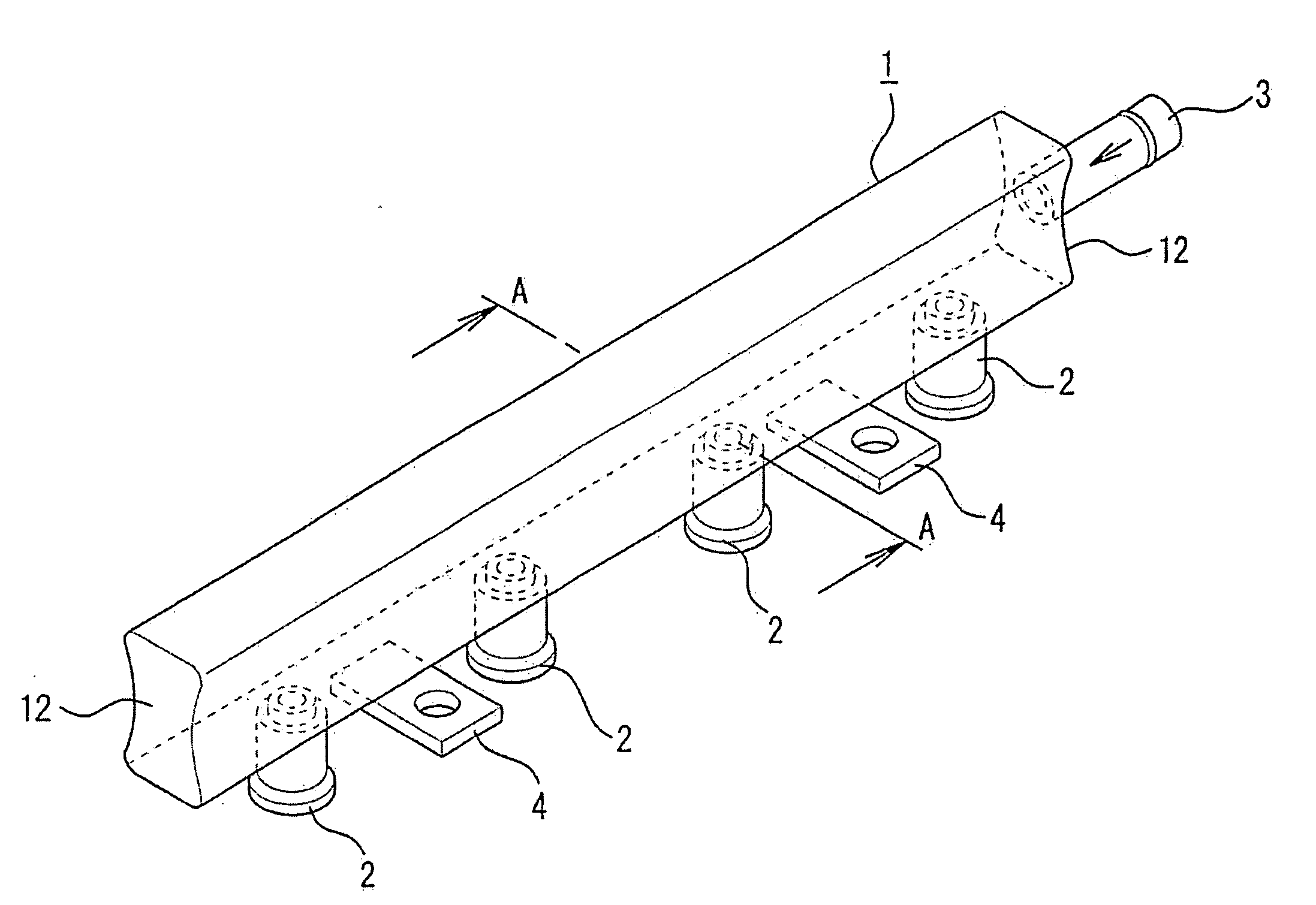
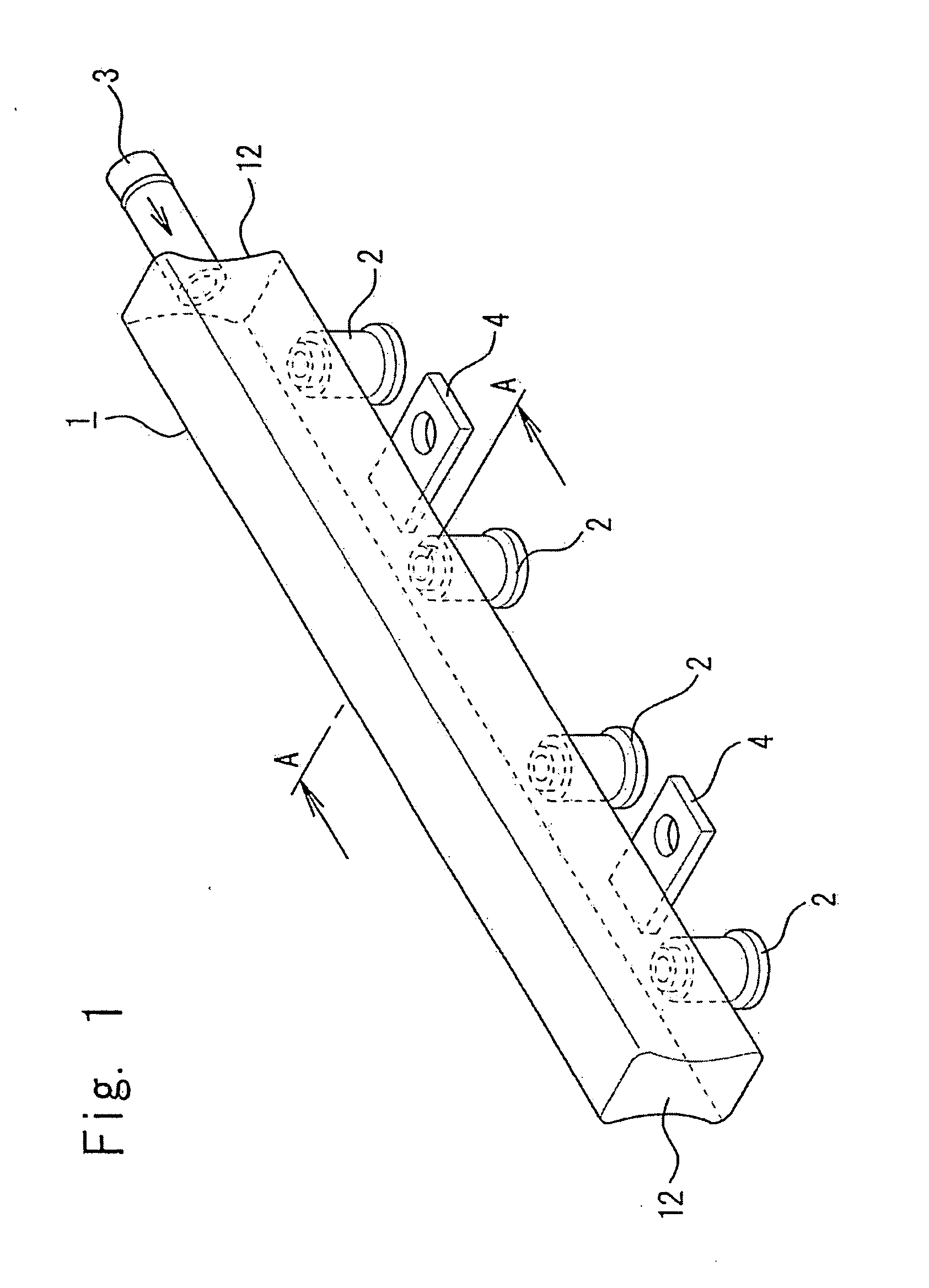
[0107] Subsequently, where the first embodiment shown in FIG. 1, FIG. 2, and FIG. 3 is described in detail, numeral 1 is a fuel delivery body, where sockets 2 capable of connecting injection nozzles, not shown, are formed on one surface of the fuel delivery body. For example, four sockets 2 are formed with predetermined intervals and angles in a case of a four-cylinder engine. Furthermore, the fuel delivery body 1 has each of ends sealed with an end cap 12, and one end is connected as secured, by means of brazing or welding, to a fuel inlet pipe 3 connected to a fuel tank, not shown, through an underfloor pipe arrangement, not shown. A return pipe for a return to the fuel tank can be formed to the other end or side surfaces of the fuel delivery body 1 but is not formed to the fuel delivery pipe of a returnless type.

[0108] Furthermore, fuel in the fuel tank is transferred through the underfloor pipe arrangement to the fuel inlet pipe 3 and then, as an arrow indicates in FIG. 1, flows...

second embodiment

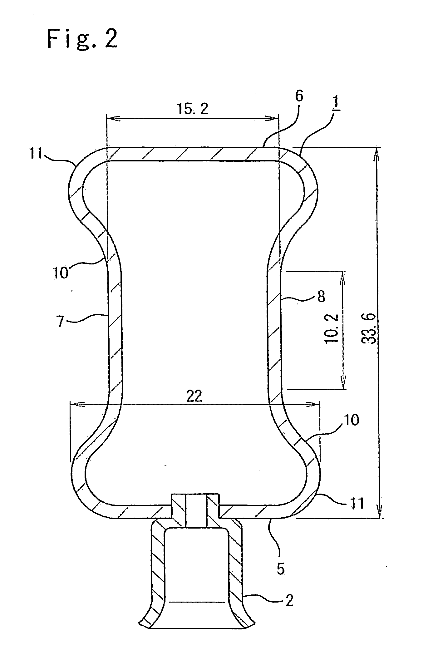
[0111] In the second embodiment shown in FIG. 4, the fuel delivery body 1 is defined as a horizontally long shape, wherein the formation width between the upper wall 6 and the lower wall 5 is set to 33.6 mm, and the height of the left side wall 7 and the right side wall 8 coupled to the upper wall 6 and the lower wall 5 through the arc shape curve portions 11 is set to 22 mm. The upper wall 6 and the lower wall 5, furthermore, are respectively bent inwardly to shape the trapezoid shape, thereby forming a pair of the absorbing wall surfaces 10. A length of the substantially straight sides of a pair of the absorbing wall surfaces 10 is set to 10.2 mm, and the outer diameter between the straight portions of the upper wall 6 and the lower wall 5 is set to 15.2 mm. As shown in the table 1, a thickness is set to 1.2 mm and a cross sectional area A inside the fuel delivery body 1 is set to 468 mm while the fuel delivery body 1 is formed with a pipe length of 325 mm, whereas the internal vo...

third embodiment

[0112] The fuel delivery body 1 according to another embodiment, the third embodiment, as shown in FIG. 5, is in the flask shape, wherein a substantially rectangular shape is mounted on a top side of the trapezoid, and the upper wall 6 and the lower wall 5 are formed as bent inwardly to form the absorbing wall surfaces 10 while the left side wall 7 and the right side wall 8 are the substantially straight sides, whereas the cross section shape of the fuel delivery body 1 is formed in a horizontally long flask shape. Furthermore, the heights of the left side wall 7 and the right side wall 8 are respectively set to 9.4 mm and 22 mm, and the outer diameter between the left side wall 7 and the right side wall 8 is set to 32 mm. The left side wall 7 and the right side wall 8 are formed as coupled through the arc shape curve portions 11 to the upper wall 6 and the lower wall 5 respectively composed of the substantially straight side and the hypotenuse. With the upper wall 6 and the lower w...


PUM


Abstract

A fuel delivery pipe capable of reducing a pressure pulsation at the time of a fuel injection due to injection nozzles, preventing vibrations and noises at an underfloor pipe arrangement, and turning down a radiate sound from the fuel delivery pipe, wherein a flexible absorbing wall surface 10 formed on a wall surface of a fuel delivery body 1 is loosened due to internal pressure changes to render internal volume of the fuel delivery body 1 increasable, αL/{square root}{square root over ( )}V determined by sonic speed αL of fuel flowing through the fuel delivery body 1 and the internal volume V of the fuel delivery body 1 is set as 20×103(m−0.5·sec−1)≦αL/{square root}{square root over ( )}V≦85×103(m−0.5·sec−1) while a ratio αLH of equivalent sonic speed αH in a high frequency area to the sonic speed αL of the fuel is set as αLH≦0.7, and the cross section shape in a perpendicular direction to an axis of the fuel delivery body 1 is formed in a substantially double side concaved shape, a substantially flask shape, a substantially trapezoid shape, a substantially key shape, and a substantially goggles shape.

Description

TECHNICAL FIELD [0001] This invention relates to a fuel delivery pipe for supplying fuel supplied from a fuel pressure pump of an engine for automobile of an electronic fuel injection type via a fuel injector, or an injection nozzle, for directly injecting each inside of intake passages and cylinders of the engine, which having an object to reduce pressure pulsations and radiant sound caused by the fuel injection. Furthermore, this invention relates to a cross-sectional structure of the fuel delivery pipe having a fuel passage, to an external structure of the fuel pipe, and to a structure, or a mechanism, for reducing the pressure pulsation and the radiant sound of the fuel delivery pipe. BACKGROUND ART [0002] Conventionally, a fuel delivery pipe having a plurality of injection nozzles to supply fuel, e.g., gasoline to a plurality of cylinders of an engine has been known. This fuel delivery pipe injects sequentially the fuel introduced from a fuel tank into a plurality of intake pip...

Claims


Application Information

Patent Timeline
Patent Type & Authority Applications(United States)
IPC IPC(8): F02M55/02F02M63/00
CPCF02M55/025F02M2200/315F02M69/465F02M55/02
Inventor USUI, MASAYOSHIWATANABE, EIJITSUCHIYA, HIKARISERIZAWA, YOSHIYUKIMIZUNO, KAZUTERUHAYASHI, KOICHIOGATA, TETSUO
Owner USUI KOKUSAI SANGYO KAISHA LTD
Why Eureka
Try Eureka