Gas pressure regulator

a gas pressure regulator and gas pressure technology, applied in fluid pressure control, process and machine control, instruments, etc., can solve the problems of reducing flow efficiency, affecting the operation, and affecting the operation of conventional gas pressure regulators, so as to improve the overall fluid flow efficiency, reduce vibration, and minimize vibration

Inactive Publication Date: 2005-11-24
VICTOR EQUIP
View PDF30 Cites 11 Cited by
  • Summary
  • Abstract
  • Description
  • Claims
  • Application Information

AI Technical Summary

Benefits of technology

[0009] According to the principles of the present invention, a gas pressure regulator having an advantageous construction and a method of using the same is provided, which may find utility in a wide variety of applications. The gas pressure regulator of the present invention is capable of minimizing vibration and improving overall fluid flow efficiency. The gas pressure regulator achieves these benefits by varying techniques including providing a nozzle having a primary pas

Problems solved by technology

Unfortunately, many conventional gas pressure regulators suffer from various disadvantages that may lead to encumbered operation, such as internal vibration or decrease flow efficiency.
However, conventional gas pressure regulators suffer from a number of disadvantages.
This force balances the forces in the regulator to achieve a desired delivery pressure and, consequently, causes the delivery pressure out of the regulator to drop as flow rate increases.
However, while speeding things up inside the regulator can make it perform better, it can also increase turbulence and vibration—two of the biggest problems in pressure regulation.
With this increase in velocity also comes an increase in turbulence—not only at the nozzle/seat area, but also inside the low-pressure cavity, as the high velocity stream coming out of the nozzle hole is diffused into the larger cavity area.
This turbulence, regardless of its origin, can have negati

Method used


Image

  • Gas pressure regulator
  • Gas pressure regulator
  • Gas pressure regulator

Examples


Embodiment Construction

[0024] The following description of the preferred embodiment is merely exemplary in nature and is in no way intended to limit the invention, its application, or uses.

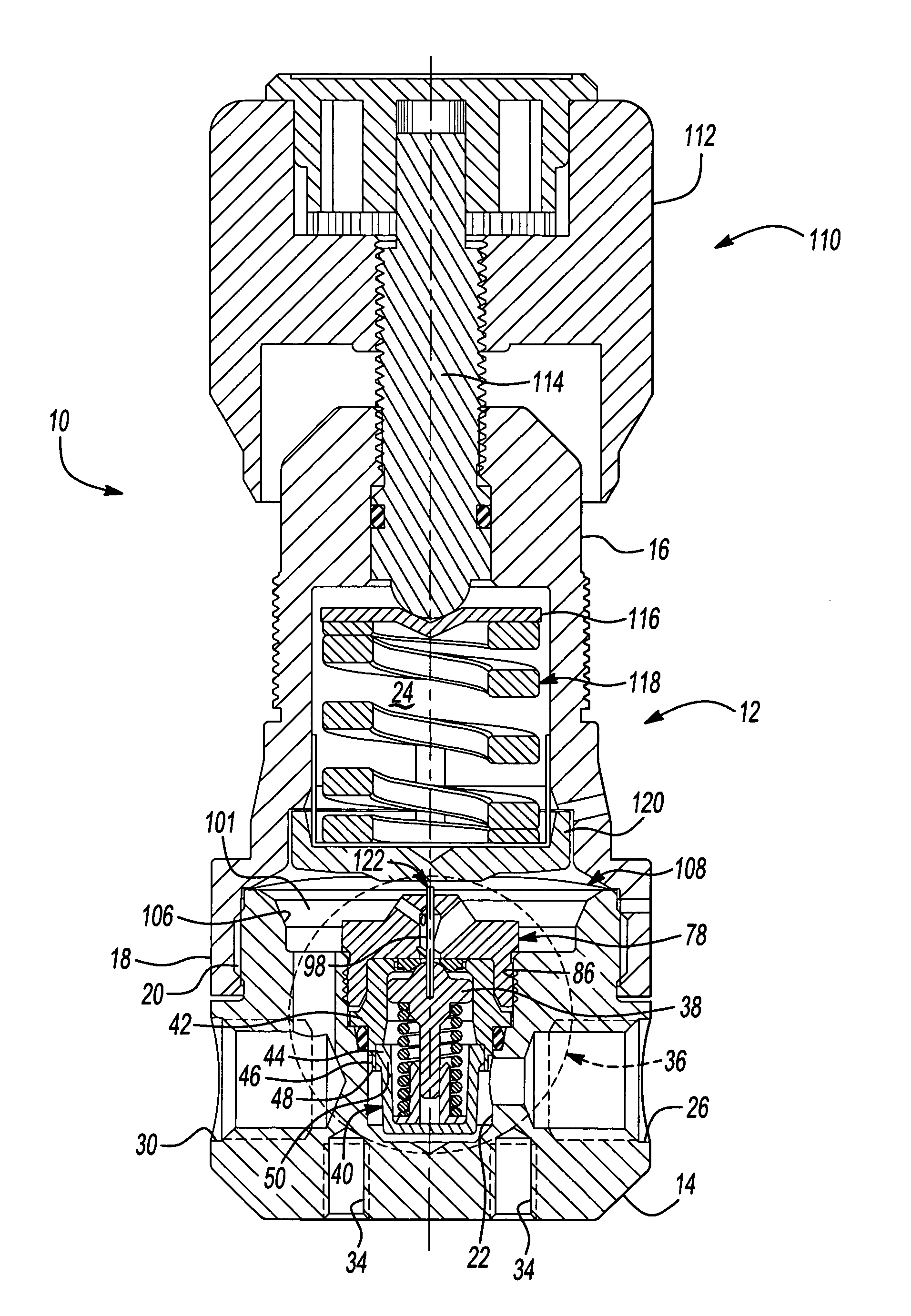
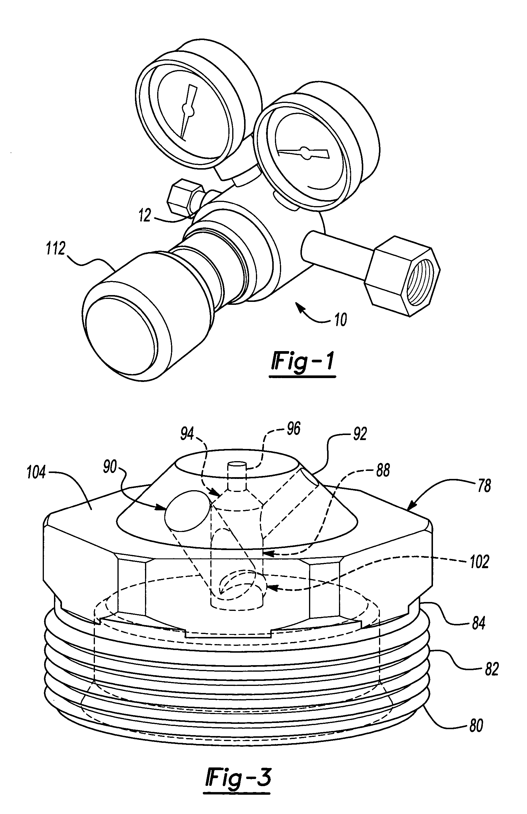
[0025] Referring now to the drawings in which like reference numerals designate like or corresponding parts throughout the several views, a gas pressure regulator, generally indicated as 10, is illustrated incorporating the principles of the present invention. As seen in FIG. 1, gas pressure regulator 10 may be used in conjunction with a pair of pressure gauges for displaying an inlet and an outlet pressure.

[0026] Referring now to FIG. 2, gas pressure regulator 10 generally includes a regulator body 12. Regulator body 12 includes a base portion 14 and an upper portion 16. Upper portion 16 of regulator body 12 defines a threaded locking flange 18 adapted to threadedly engage corresponding threads 20 formed on base portion 14 of regulator body 12 to permit reliable and simple coupling of base portion 14 and upper portio...


PUM


Abstract

A gas pressure regulator capable of minimizing vibration and improving overall fluid flow efficiency. The gas pressure regulator achieves these benefits using varying techniques including providing a nozzle having a primary passage, a secondary passage, and a flow channel groove to smooth the fluid flow, reduce turbulence, and improve overall flowrate, without adversely effecting the necessary backpressure required for reliable operation. Additionally, the gas pressure regulator may use angled walls in the low-pressure cavity to enhance deflection and distribution. Still further, the gas pressure regulator may use additional flow channels to permit smooth fluid flow while eliminating fluid impact.

Description

FIELD OF THE INVENTION [0001] The present invention generally relates to gas pressure regulators and, more particularly, relates to a gas pressure regulator capable of decreasing internal vibration and increasing flow efficiency therethrough to provide improved flow performance. BACKGROUND OF THE INVENTION [0002] In many situations, gas pressure regulators are used to control and / or maintain a desired fluid flow and pressure for use in operating a wide variety of machines, devices, and the like. In this regard, it is desirable for gas pressure regulators to provide a stable and consistent fluid flow rate and / or fluid pressure so as not to hinder the operation of or damage downstream machines or devices. Unfortunately, many conventional gas pressure regulators suffer from various disadvantages that may lead to encumbered operation, such as internal vibration or decrease flow efficiency. [0003] Conventional gas pressure regulators generally include a valve assembly that is selectively...

Claims


Application Information

Patent Timeline
IPC IPC(8): G05D16/04G05D16/06
CPCG05D16/0666Y10T137/7818
Inventor BOYER, ROBERTMADEWELL, TOMMY
Owner VICTOR EQUIP
Why Eureka
Try Eureka