End winding restraint in an electrical machine

a technology of end windings and electrical machines, applied in the field of electrical machines, can solve the problems of axial displacement, elliptical deformation, loss of concentricity, etc., and achieve the effect of preventing rotor imbalan

Inactive Publication Date: 2005-11-24
GENERAL ELECTRIC CO
View PDF32 Cites 4 Cited by
  • Summary
  • Abstract
  • Description
  • Claims
  • Application Information

AI Technical Summary

Benefits of technology

[0003] In accordance with a preferred embodiment of the present invention, the rotor body has field windings and end windings which are restrained against both axial and circumferential movement. Particularly, the rotor body includes beams secured to an end face of the rotor body and which beams extend axially for securement to an annular end disk. Between the rotor end face and the annular end disk are a plurality of circumferentially spaced rakes mounted on the beams. The rakes include a plurality of axially spaced tines for receiving the end windings. The rakes and end disk restrain the end windings against axial movement. The end disk is also weighted such that the tendency of the end windings to become distorted, i.e., elliptically deformed and lose concentricity at speed, is effectively resisted. The end disk is weighted symmetrically in a diametrical direction to preclude imbalance of the rotor. The end disk also includes generally radially extending passages along the inner face which weight the portions of the disk not having passages. The passages also provide for transmission of cooling fluid generally radially outwardly and through apertures in the enclosure about the rotor body.
[0004] In accordance with a preferred embodiment according to the present invention, there is provided a restraint arrangement for end windings of a rotor in an electrical machine comprising an end winding support having a plurality of axially extending, circumferentially spaced support beams secured at one end to the rotor against movement in an axial direction and a plurality of circumferentially spaced, axially extending support rakes radially outwardly of respective beams for receiving the circumferentially extending end windings between axially spaced tines of the rakes and restraining the end windings against axial movement.

Problems solved by technology

In both types of generator constructions, the end windings can become distorted, i.e., elliptically deformed and lose concentricity if not supported.
Also, the end windings have a tendency to displace axially when the generator is operated at speed.

Method used


Image

  • End winding restraint in an electrical machine
  • End winding restraint in an electrical machine
  • End winding restraint in an electrical machine

Examples


Embodiment Construction

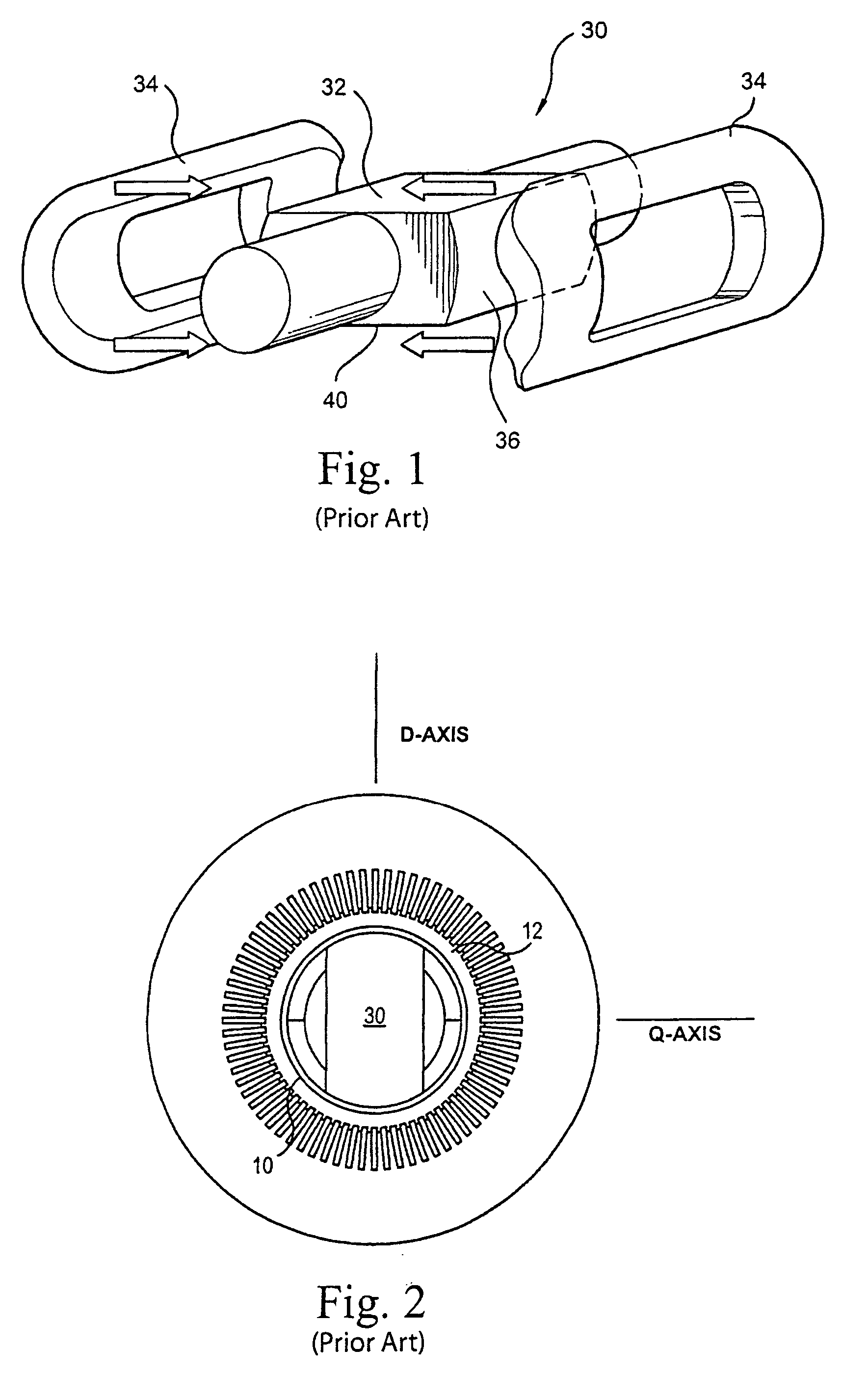
[0013] As illustrated in drawing FIGS. 1 and 2, a generator rotor 30 includes a multi-pole magnetic core 32 (a two-pole core being shown) and a plurality of prefabricated winding assemblies 34, one for each pole, and corresponding pole faces 36. The construction and materials of the magnetic core 32 and winding assemblies 34 are known. The prefabricated winding assemblies are disposed over the parallel side forging forming the rotor body 40, and are curved in an arc generally concentric with the rotor body. As illustrated in FIG. 2, the rotor is disposed within a stator and an air gap 12 exists between an enclosure 10 about the rotor and the inner surface of the stator. For orientation purposes, there is illustrated in FIG. 2 a quadrature axis Q extending normal to both the axis of rotation of the rotor and the flat side surfaces. The direct axis D extends normal to the Q axis and the axis of rotation. While the present specification discloses an advanced carbon fiber rotor enclosur...


PUM


Abstract

The rotor body of an electrical machine has end windings supported by a plurality of circumferentially spaced rakes having tines between which the end windings pass in an arcuate pattern from and for return to an axial orientation within the rotor body. The rakes are supported on axial beams secured to the rotor body. An end disk is secured at the opposite ends of the beams and to a shield overlying the end windings. The rakes, beams and end disks provide axial end winding restraint. The end disk is weighted at selected circumferential locations to resist tendencies of the end windings to distort, e.g., toward an elliptical or non-concentric configuration about the rotor axis.

Description

BACKGROUND OF THE INVENTION [0001] The present invention relates generally to electrical machines of the type having a rotor and field windings, including end windings about the rotor body and particularly relates to restraints for restraining axial movement of the end windings and minimizing distortion of the rotor end windings in circumferential and axial directions. [0002] In electrical machines, for example, generators, there is provided a rotor body having field windings which in part extend from the rotor body to form arcs at the opposite ends of the rotor body called end windings. The end windings extend generally axially from the rotor body and cross over supports or spindles in a circumferential direction adjacent opposite ends of the body for return in an axial direction into and along the rotor body. In a typical generator construction, the windings are located in slots in the rotor body and wedges secure the windings in the slots. The end windings are typically separated...

Claims


Application Information

Patent Timeline
Patent Type & Authority Applications(United States)
IPC IPC(8): H02K3/51H02K3/46H02K3/50
CPCH02K3/505
Inventor KAMINISKI, CHRISTOPHER ANTHONYNYGARD, ROBERT JOHNTANAVDE, ANAND SHANKARALEXANDER, JAMES PELLEGRINO
Owner GENERAL ELECTRIC CO
Why Eureka
Try Eureka