Fluid flow pulsing for increased stability in PEM fuel cell

a technology of pem fuel cell and fluid flow, which is applied in the field of fuel cells, can solve the problems of reducing system efficiency, inability to operate the fuel cell stack, and waste of high-grade reactants, and achieves the effects of increasing the efficiency of the system

Inactive Publication Date: 2005-11-24
GENERAL MOTORS COMPANY
View PDF13 Cites 56 Cited by
  • Summary
  • Abstract
  • Description
  • Claims
  • Application Information

AI Technical Summary

Benefits of technology

[0008] Accordingly, the present invention provides a fuel cell system including a fuel cell stack and a flow control device that controls a supply of a first phase fluid flowing through the fuel cell stack. A controller monitors at least one parameter of the fuel cell stack and controls the supply to generate pulses of reactant when the at least one parameter crosses a threshold value to flush a second phase fluid from said fuel cell stack.

Problems solved by technology

The liquid phase fluid impedes flow of the gas phase reactant fluids, which can result in unstable operation of the fuel cell stack.
This presents a significant disadvantage, however, in that a high percentage of the reactant is wasted.
As a result, system efficiency is decreased.
The gas phase fluid impedes flow of the liquid phase heat transfer fluid, which can result in localized temperature increases or hot spots within the fuel cell stack.
These hot spots, reduce the durability of the fuel cell stack and can result in localized damage to the fuel cell stack.

Method used


Image

  • Fluid flow pulsing for increased stability in PEM fuel cell
  • Fluid flow pulsing for increased stability in PEM fuel cell
  • Fluid flow pulsing for increased stability in PEM fuel cell

Examples


Embodiment Construction

[0025] The following description of the preferred embodiments is merely exemplary in nature and is in no way intended to limit the invention, its application, or uses.

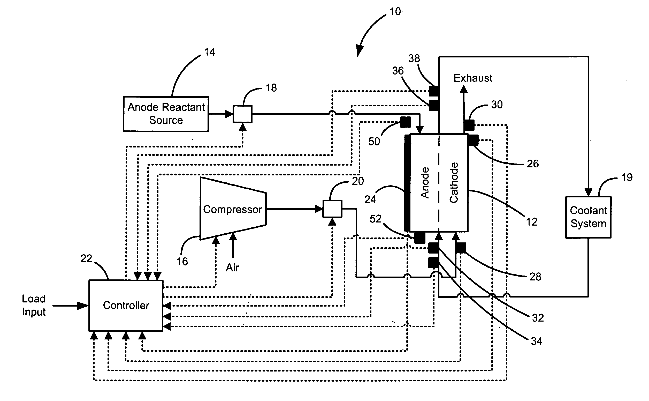
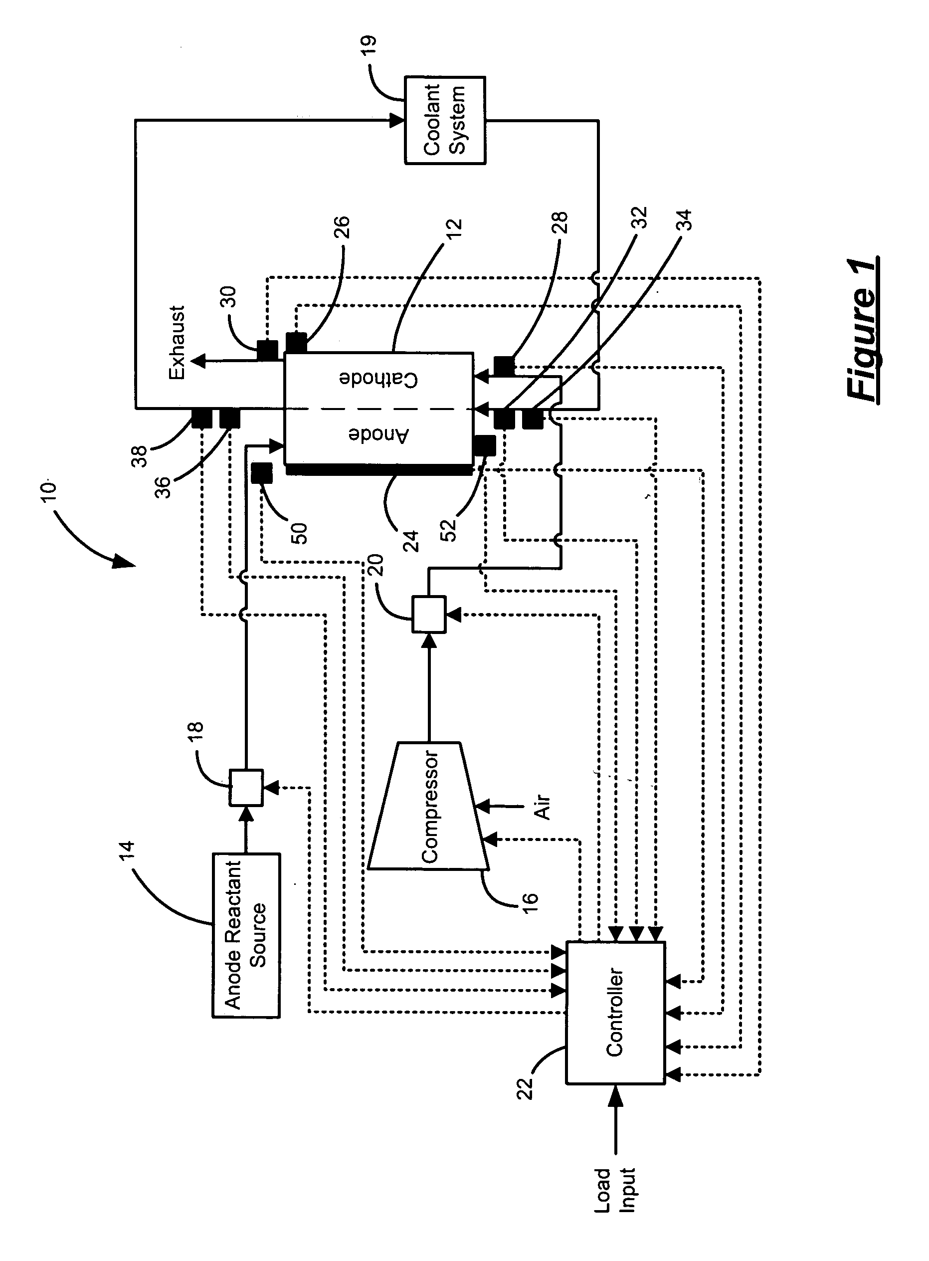
[0026] Referring now to FIG. 1, an exemplary fuel cell system 10 is illustrated. The fuel cell system 10 includes a fuel cell stack 12 that process reactants to generate electricity. More specifically, the fuel cell stack 12 includes an anode side through which an anode reactant flows and a cathode side through which a cathode reactant flows. The anode reactant is supplied by an anode reactant source 14 and generally includes hydrogen or a hydrogen-rich reformate. The cathode reactant is generally provided as oxygen-rich air supplied by a compressor 16. An anode control device (FCD) 18, such as a regulator, regulates anode reactant flow to the fuel cell stack 12. A cathode FCD 20, such as a regulator, regulates cathode reactant flow to the fuel cell stack 12. The anode and cathode reactant fluids flow through the fuel...


PUM

PropertyMeasurementUnit
average cell voltageaaaaaaaaaa
voltagesaaaaaaaaaa
voltagesaaaaaaaaaa

Abstract

A fuel cell system includes a fuel cell stack and a flow control device that controls a supply of a first phase fluid flowing through the fuel cell stack. A controller monitors at least one parameter of the fuel cell stack and controls the supply to generate pulses of reactant when the at least one parameter crosses a threshold to flush a second phase fluid from said fuel cell stack.

Description

FIELD OF THE INVENTION [0001] The present invention relates to fuel cells, and more particularly to regulating reactant and coolant flows to increase stability of a fuel cell. BACKGROUND OF THE INVENTION [0002] Fuel cells produce electricity through electrochemical reaction and have been used as power sources in many applications. Fuel cells can offer significant benefits over other sources of electrical energy, such as improved efficiency, reliability, durability, cost and environmental benefits. Fuel cells may, eventually be used in automobiles and trucks. Fuel cells may also power homes and businesses. [0003] There are several different types of fuel cells, each having advantages that may make them particularly suited to given applications. One type is a proton exchange membrane (PEM) fuel cell, which has a membrane sandwiched between an anode and a cathode. The membrane and respective electrodes together in an assembly are referred to as a membrane electrode assembly (MEA). To p...

Claims


Application Information

Patent Timeline
Patent Type & Authority Applications(United States)
IPC IPC(8): H01M8/04H01M50/77
CPCH01M8/04179Y02E60/50H01M8/04358H01M8/04388H01M8/04395H01M8/04402H01M8/0441H01M8/04417H01M8/04432H01M8/04552H01M8/04559H01M8/04619H01M8/04641H01M8/04753H01M8/04768H01M8/04231
Inventor CHAPMAN, IVAN DARYLMACKINTOSH, CHARLESRAPAPORT, PINKHAS A.
Owner GENERAL MOTORS COMPANY
Why Eureka
Try Eureka