Method and apparatus for determining position and orientation

Inactive Publication Date: 2005-11-24
CANON KK
View PDF3 Cites 38 Cited by
  • Summary
  • Abstract
  • Description
  • Claims
  • Application Information

AI Technical Summary

Benefits of technology

[0047] The present invention provides a method and an apparatus for determining position and orientation of an imaging device even when the number of ind

Problems solved by technology

Each of these orientation sensor units generates a drift error which accumulates with time.
Therefore, if the input image does not include enough image information to perform stable registration, for example, when the indices are collected in a relatively narrow area of the image, when only three indices are detected, or when errors occur in the index detection, there is a risk that s

Method used


Image

  • Method and apparatus for determining position and orientation
  • Method and apparatus for determining position and orientation
  • Method and apparatus for determining position and orientation

Examples


Example

First Embodiment

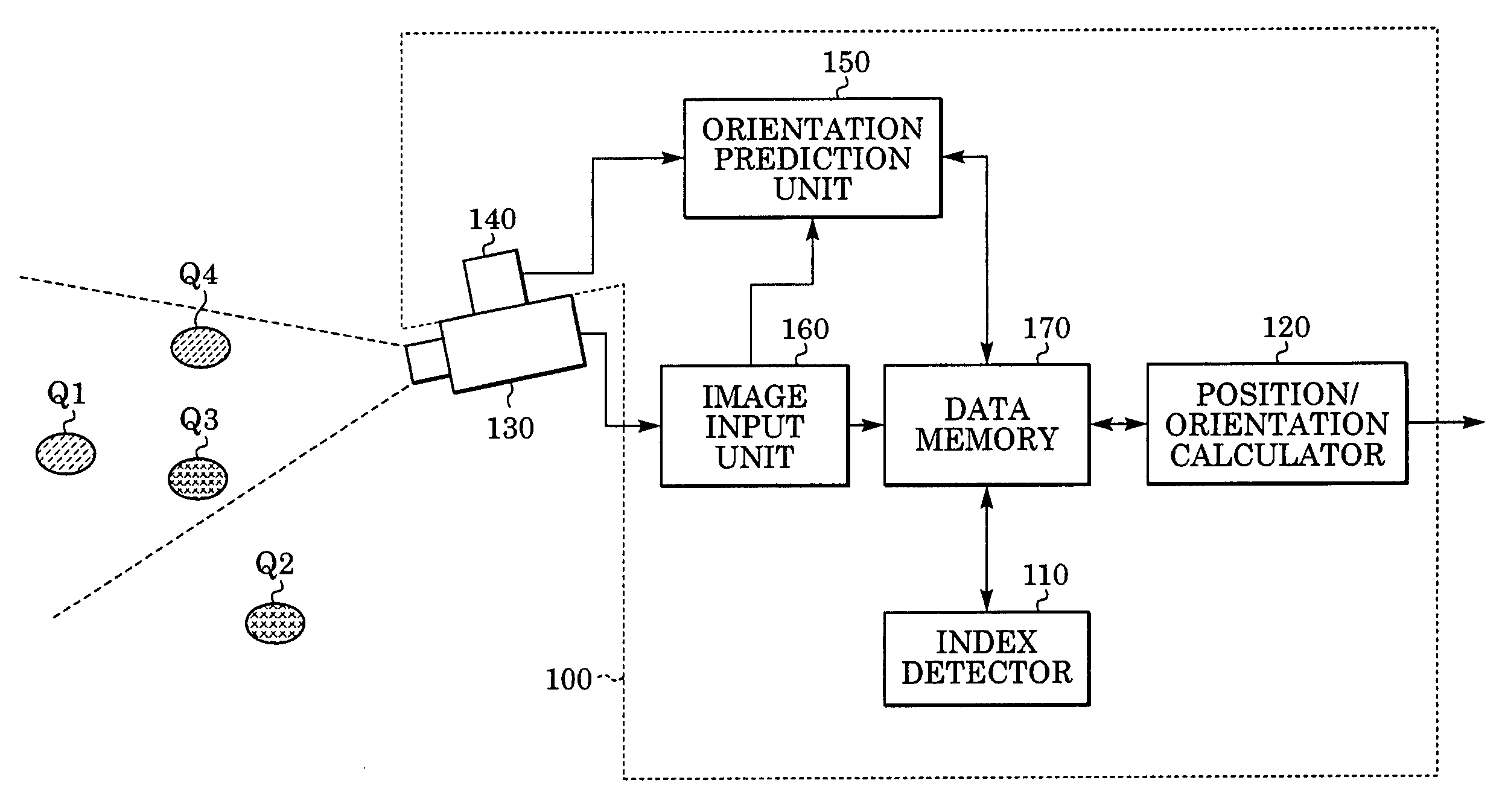
[0062] A position / orientation determination apparatus according to a first embodiment determines a position and an orientation of an imaging device. The position / orientation determination apparatus and a position / orientation determination method according to the present embodiment will be described below.

[0063]FIG. 4 shows the structure of the position / orientation determination apparatus according to the present embodiment. As shown in FIG. 4, the position / orientation determination apparatus 400 according to the present embodiment includes an image input unit 160, a data memory 170, an index detector 110, an orientation sensor unit 140, an orientation prediction unit 450, and a position / orientation calculator 420, and is connected to an imaging device 130. In addition, indices to be shot by the imaging device 130 are arranged at a plurality of positions in a real space, similar to the above-described known structure. Operations of the elements denoted by the same r...

Example

Second Embodiment

[0101] In the first embodiment, the position and orientation of the imaging device itself which moves in a space are determined. In comparison, a position / orientation determination apparatus according to a second embodiment determines a position and an orientation of an arbitrary target object, and is structured such that a camera for obtaining a shot image is attached to the position / orientation determination apparatus according to the first embodiment. The position / orientation determination apparatus and a position / orientation determination method according to the second embodiment are described below.

[0102]FIG. 8 shows the structure of the position / orientation determination apparatus according to the present embodiment. As shown in FIG. 8, the position / orientation determination apparatus 800 according to the present embodiment includes an image input unit 160, a data memory 170, an index detector 110, an orientation sensor unit 140, an orientation prediction un...

Example

Third Embodiment

[0109] In the above-described embodiments, the update value φ for the azimuth-drift-error correction value of the orientation sensor unit is determined as an unknown parameter. However, when the orientation sensor unit has high accuracy, when the orientation sensor unit is used only for a short time, or when the update value for the azimuth-drift-error correction value can be input manually, parameters to be determined by the position / orientation calculator may be limited to the position of the imaging device. A position / orientation determination apparatus according to a third embodiment determines a position and an orientation of an imaging device, and is structured similarly to the position / orientation determination apparatus according to the first embodiment except for the function of the position / orientation calculator 420. The position / orientation determination apparatus and a position / orientation determination method according to the third embodiment are descr...


PUM


Abstract

An index detector detects image coordinates of indices arranged on a scene from an image shot by an imaging device. An orientation sensor is attached to the imaging device, and outputs a measured orientation. An orientation prediction unit predicts an orientation of the imaging device on the basis of the measured orientation obtained by the orientation sensor. A position/orientation calculator receives the predicted orientation of the imaging device and a set of the image coordinates and world coordinates of each index, determines the position of the imaging device and an update value for an azimuth-drift-error correction value of the orientation sensor, and calculates the position and orientation of the imaging device.

Description

BACKGROUND OF THE INVENTION [0001] 1. Field of the Invention [0002] The present invention relates to a technique for determining a position and an orientation of an object. [0003] 2. Description of the Related Art [0004] Recently, a significant amount of research has been done on mixed reality which aims at a seamless synthesis of a real space and a virtual space. Mixed reality may be shown on an image display device by a video see-through method in which an image of a virtual space (for example, virtual objects drawn by computer graphics or textual information) is superimposed on an image of a real space shot by an imaging device, such as a video camera. The virtual space is generated depending on the position and orientation of the imaging device. [0005] In addition, mixed reality may also be shown on an optical see-through display attached to the head of a viewer by an optical see-through method in which an image of a virtual space generated depending on the position and orientat...

Claims


Application Information

Patent Timeline
IPC IPC(8): G01C19/00G06T7/00
CPCG06K9/3208G06T7/0042G06K9/3216G06T7/73G06V10/242G06V10/245
Inventor SATOH, KIYOHIDEUCHIYAMA, SHINJI
Owner CANON KK
Why Eureka
Try Eureka