Transparent biopsy punch

a biopsy and transparent technology, applied in the field of biopsy punches, can solve the problems of not allowing convenient simultaneous viewing of tissue at or outside the cutting edge, and achieve the effect of optimal leverage and higher negative or clear surgical margins

Inactive Publication Date: 2005-11-24
HUOT INSTR
View PDF11 Cites 8 Cited by
  • Summary
  • Abstract
  • Description
  • Claims
  • Application Information

AI Technical Summary

Benefits of technology

[0003] A skin biopsy punch has a transparent cutting edge, allowing a user to view a patient's skin in and around a portion to be cut. In one embodiment, the cutting edge allows viewing of a skin lesion and the lesion's margins. By viewing the margins, the lesion may be cleanly removed or excised with a higher rate of negative or clear surgical margins.

Problems solved by technology

However, these devices do not allow convenient simultaneous viewing of the tissue at or outside the cutting edge.

Method used


Image

  • Transparent biopsy punch
  • Transparent biopsy punch
  • Transparent biopsy punch

Examples


Embodiment Construction

[0011] In the following description, reference is made to the accompanying drawings that form a part hereof, and in which is shown by way of illustration specific embodiments in which the invention may be practiced. These embodiments are described in sufficient detail to enable those skilled in the art to practice the invention, and it is to be understood that other embodiments may be utilized and that structural changes may be made without departing from the scope of the present invention. Dimensions shown in the drawings may be exaggerated to more clearly show certain aspects, and such dimensions should not be taken as limiting of the scope of the invention. The following description is, therefore, not to be taken in a limited sense, and the scope of the present invention is defined by the appended claims.

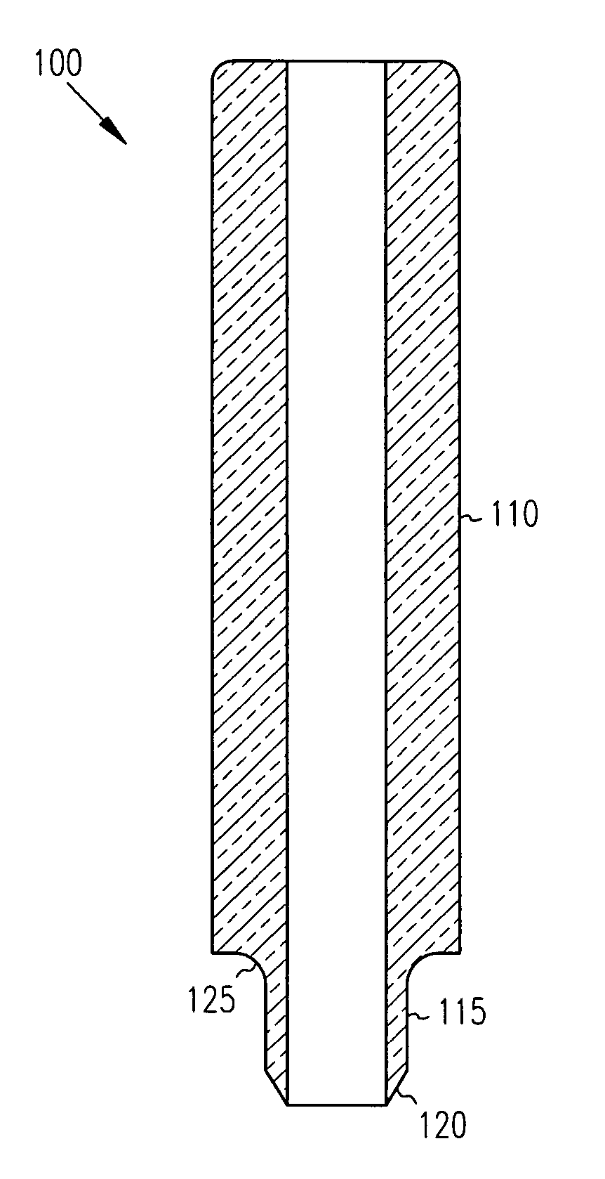
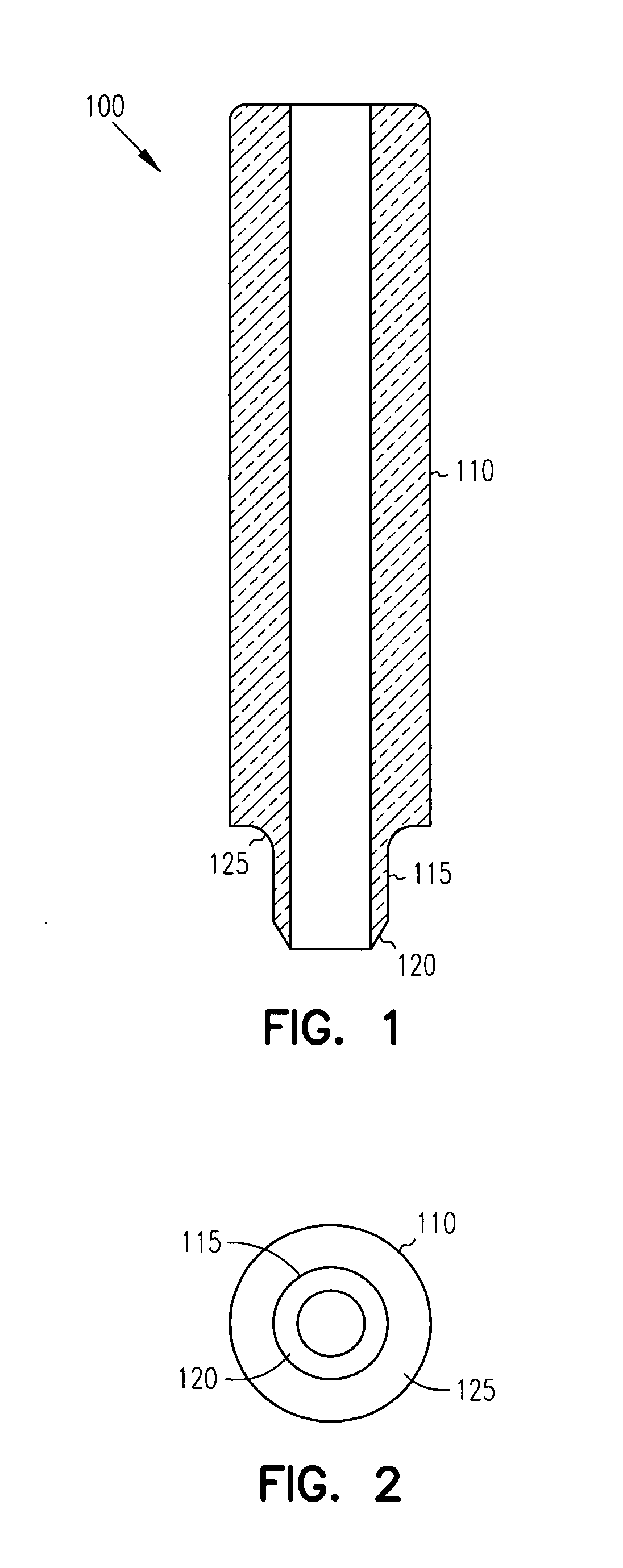
[0012]FIG. 1 shows a single piece biopsy punch generally at 100. Punch 100 has a handle 110 for gripping and manipulating the punch by hand or with other devices as desired. The...


PUM


Abstract

A skin biopsy punch has a transparent cutting edge, allowing a user to view a patient's skin in and around a portion to be cut. In one embodiment, the cutting edge allows viewing of a skin lesion and the lesion's margins. By viewing the margins, the lesion may be cleanly removed or excised with a higher rate of negative or clear surgical margins.

Description

FIELD OF THE INVENTION [0001] The present invention relates to biopsy punches, and in particular to a transparent biopsy punch. BACKGROUND OF THE INVENTION [0002] A skin biopsy punch is a device which samples a piece of skin. Biopsy punches have taken many different forms, with common punches having a cylindrical metal cutting blade that is circular or elliptical in shape. The blades may have a beveled cutting edge. Some punches are formed with an aperture or window positioned over the top of the cutting edge, allowing one to look down inside the blade to view tissue as it is being cut. However, these devices do not allow convenient simultaneous viewing of the tissue at or outside the cutting edge. SUMMARY OF THE INVENTION [0003] A skin biopsy punch has a transparent cutting edge, allowing a user to view a patient's skin in and around a portion to be cut. In one embodiment, the cutting edge allows viewing of a skin lesion and the lesion's margins. By viewing the margins, the lesion ...

Claims


Application Information

Patent Timeline
Patent Type & Authority Applications(United States)
IPC IPC(8): A61B10/00A61B10/02A61B17/32A61B17/322A61B19/00
CPCA61B10/02A61B2017/00902A61B17/32053A61B10/0233
Inventor WITTENBERG, GREGORY P.
Owner HUOT INSTR
Why Eureka
Try Eureka